Bone mill including a base and a mill head separate from the base, the mill head including a moveable catch tray

a mill head and mill head technology, applied in the field of bone mills, can solve the problems of frictional heat such contact can generate and damage the chip, and achieve the effect of minimizing costs

Active Publication Date: 2009-05-07
STRYKER CORP
View PDF32 Cites 55 Cited by
  • Summary
  • Abstract
  • Description
  • Claims
  • Application Information

AI Technical Summary

Benefits of technology

[0017]The mill head of this invention has features that minimize the extent to which the formed bone chips adhere to the cutting disc and the other surfaces of the mill head. These features thus ensure, to a significant extent that the chips formed by the mill head enter the catch tray so they can be used in the procedure.
[0018]Still another feature of the bone mill of this invention is that once a chip is cut from the bone, it does not again strike the cutting disc. This minimal contact with the...

Problems solved by technology

This minimal contact with the cutting disc reduces the likelihoo...

Method used


Image

  • Bone mill including a base and a mill head separate from the base, the mill head including a moveable catch tray
  • Bone mill including a base and a mill head separate from the base, the mill head including a moveable catch tray
  • Bone mill including a base and a mill head separate from the base, the mill head including a moveable catch tray

Examples


Embodiment Construction

I. Overview

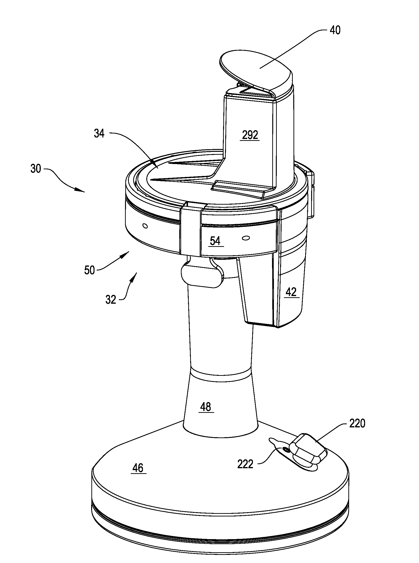
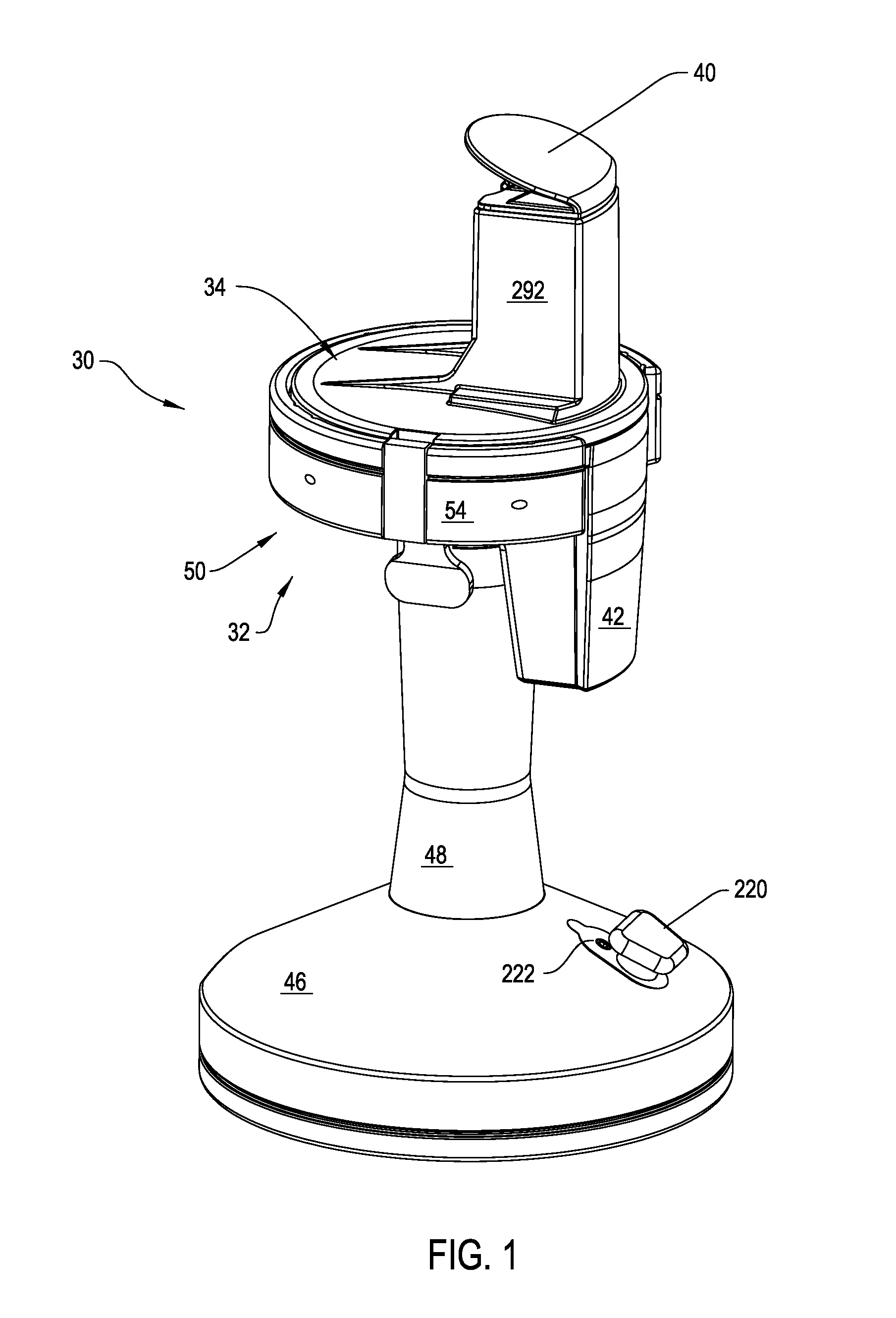
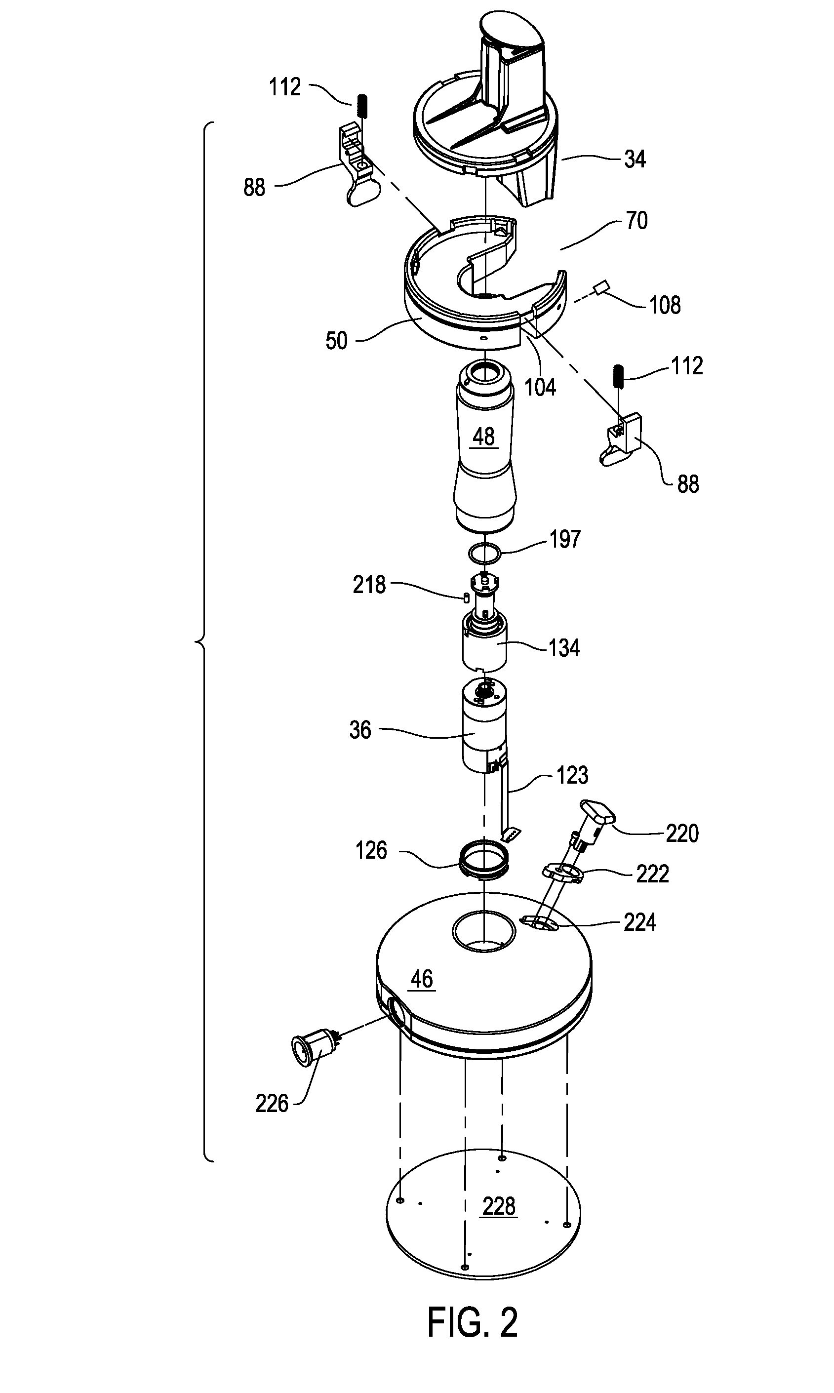
[0048]As seen by reference to FIG. 1 a bone mill 30 of this invention includes a base 32 to which a mill head 34 is removably attached. Internal to the base 32 is a motor 36 (FIG. 2). A generally planner shaped cutting disc 38 (FIG. 18) is disposed inside the mill head 34. A plunger 40 is mounted to the top of the mill head 34. Disposed below the plunger 40, below the underside of the cutting disc 38 is removable catch tray 42. Bone mill 30 is used by actuating the motor 36 so that the motor rotates disc 38. Plunger 40 is used to press bone against the rotating disc 38 so as to result in the formation of bone chips. These chips fall into catch tray 42 so that the chips are available for use in a surgical procedure.

II. Base

[0049]The base 30, as seen in FIGS. 1 and 2, includes a circular foot 46. A leg 48, having a circular cross section, extends upwardly from foot 46. In the illustrated version of the invention, the top of the foot 46 has a frusto-conical, inwardly tapered...


PUM


Abstract

A bone mill including a base and a mill head that is removably attached to the base. A cutting disc is rotatably disposed in the mill head. When the mill head is attached to base, the cutting disc is rotated by a motor internal to the base. A plunger mounted to the mill head urges the bone against the cutting disc. The cutting disc and an impingement plate internal to the mill head shear the bone into chips. The chips are discharged from an opening in the mill head into a catch tray removably attached to the mill head.

Description

FIELD OF THE INVENTION[0001]This invention relates generally to a bone mill used to reduce the size of bone used in surgical procedures. More particularly, this invention is generally related to a bone mill that includes a base and a mill unit that is removably attached to the base.BACKGROUND OF THE INVENTION[0002]A bone mill is a medical device that, as its name implies, reduces the size of section of bone. The milled bone, which is often chip sized, is used in a medical procedure as a filler adjacent other sections of bone. For example, in a spinal fusion procedure, it is a known practice to place a compound formed out of milled bone around the rods used to hold adjacent vertebra in alignment. This compound serves as a lattice upon which the tissues forming the vertebra grow so as to form a bone-link between these vertebras. This link minimizes the load imposed on the rods. Milled bone is similarly used as filler and / or growth formation lattice in orthopedic surgical procedures an...

Claims


Application Information

Patent Timeline
IPC IPC(8): A61B17/00A61B17/32
CPCA61B2017/1602A61F2/4644A61F2002/4645A61B17/1615B02C18/22B02C18/24B02C18/16A61F2002/4646
Inventor BURMEISTER, III, RICHARD FREDERICKKALINKA, GARY T.PETERSON, MICHAEL J.
Owner STRYKER CORP
Why Eureka
Try Eureka