
Heart Valve Prosthesis

a heart valve and prosthesis technology, applied in the field of artificial heart valves, can solve the problems of increasing the risk of blood clot, increasing the likelihood of early failure of the implant, increasing the burden on the heart, etc., and achieves the effects of reducing or eliminating the formation of stagnant zones, reducing or minimizing blood flow turbulence, and long and reliable servi

Inactive Publication Date: 2009-05-07
SAMKOV ALEXANDER
View PDF1 Cites 34 Cited by
  • Summary
  • Abstract
  • Description
  • Claims
  • Application Information

AI Technical Summary

Benefits of technology

[0014]The invention has many advantages. For instance, the tri-leaflet artificial heart valve prosthesis disclosed herein resembles the human aortic valve and is expected to provide long and reliable service. The invention decreases or minimizes blood flow turbulence and reduces or eliminates formation of stagnant zones. It provides for a controlled reverse flow, thereby reducing or preventing blood clotting. In preferred embodiments, six cylindrical surfaces are used to shape the upper region of the annulus. Together with the three leaflets, the cylindrical surfaces give rise to essentially independent blood flow channels for washing or flushing the hinges that connect the leaves to the annulus, thus reducing the likelihood of thromboembolism. Other aspects of the invention promote good opening and closing conditions and minimize blood recirculation. Furthermore, the invention can reduce hydraulic resistance and improve the utilization of the valve cross sectional area. In specific aspects the invention also relates to an artificial heart valve prosthesis having an easy to manufacture casing.

Problems solved by technology

Deficiencies associated with bi-leaflet designs include turbulence, velocity gradients, non-synchronous opening of the leaflets and recirculation of the blood resulting in an increased burden on the heart.
Some tri-leaflet heart valve designs promote formation of stagnant zones in the blood flow, thus increasing the danger of blood clotting.
Designs that place a high mechanical load on the hinge mechanisms result in an increased likelihood of early failure of the implant.
Difficult machining-is-still another disadvantage associated with some of the existing tri-leaflet heart valves.

Method used


Image

  • Heart Valve Prosthesis
  • Heart Valve Prosthesis
  • Heart Valve Prosthesis

Examples


Embodiment Construction

[0022]The above and other features of the invention including various novel details of construction and combinations of parts, and other advantages, will now be more particularly described with reference to the accompanying drawings and pointed out in the claims. It will be understood that the particular method and device embodying the invention are shown by way of illustration and not as a limitation of the invention. The principles and features of this invention may be employed in various and numerous embodiments without departing from the scope of the invention.

[0023]The invention generally relates to artificial heart valve prostheses. More specifically, the invention relates to tri-leaflet mechanical heart valves.

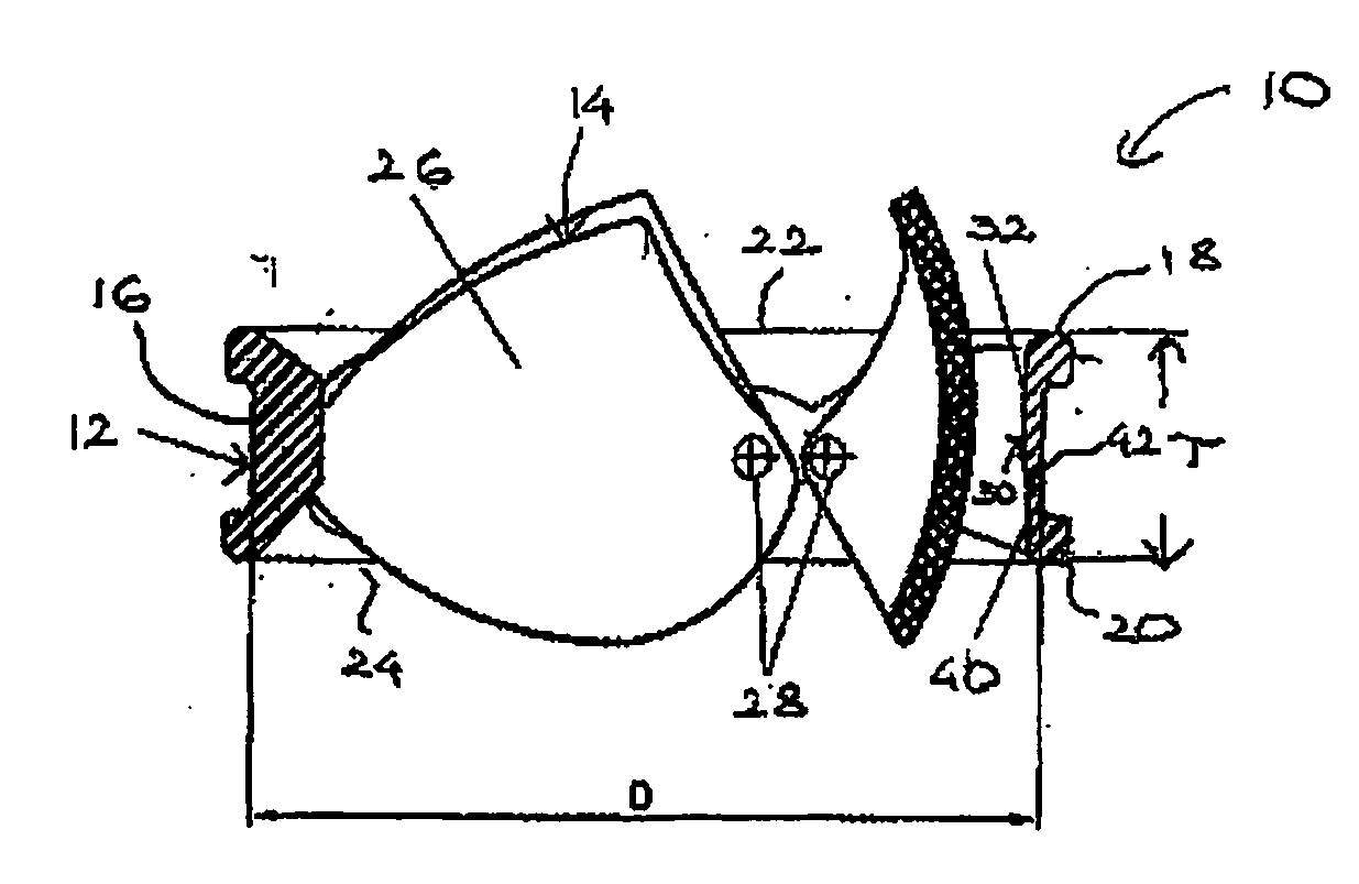
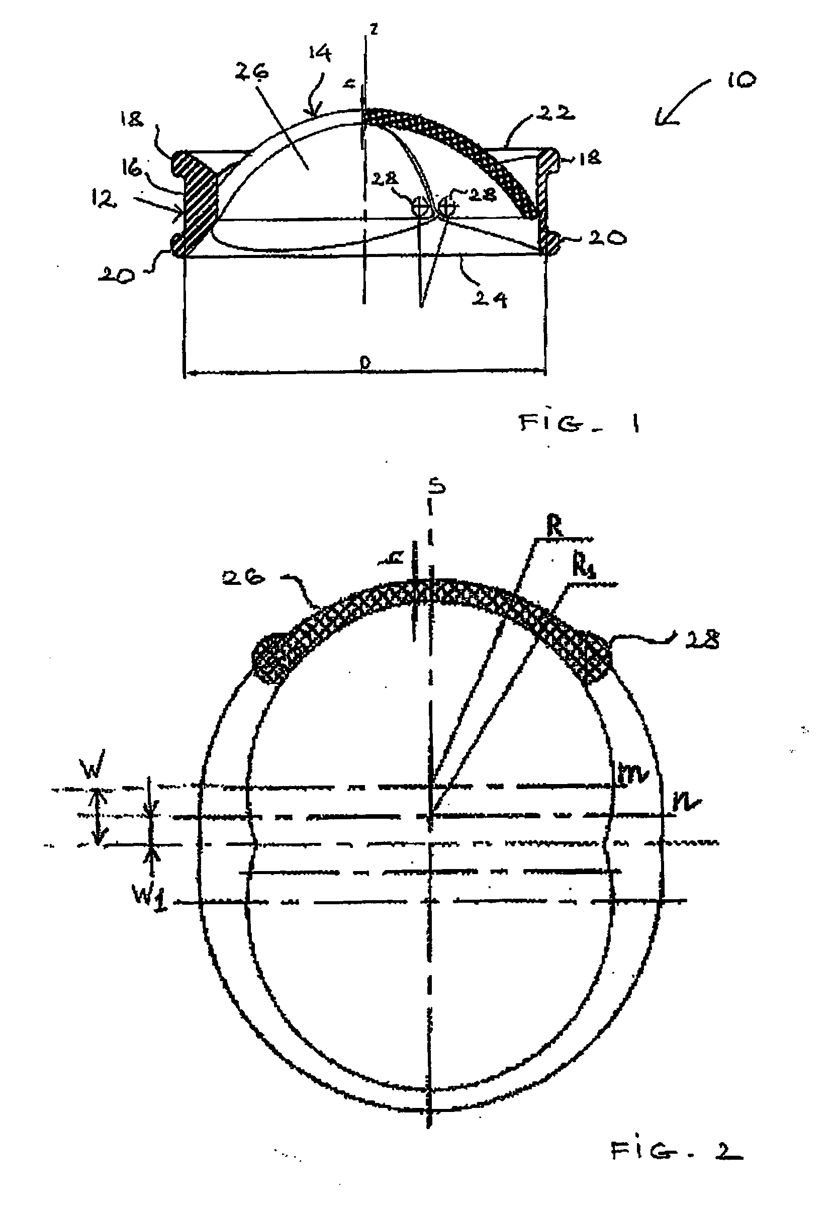
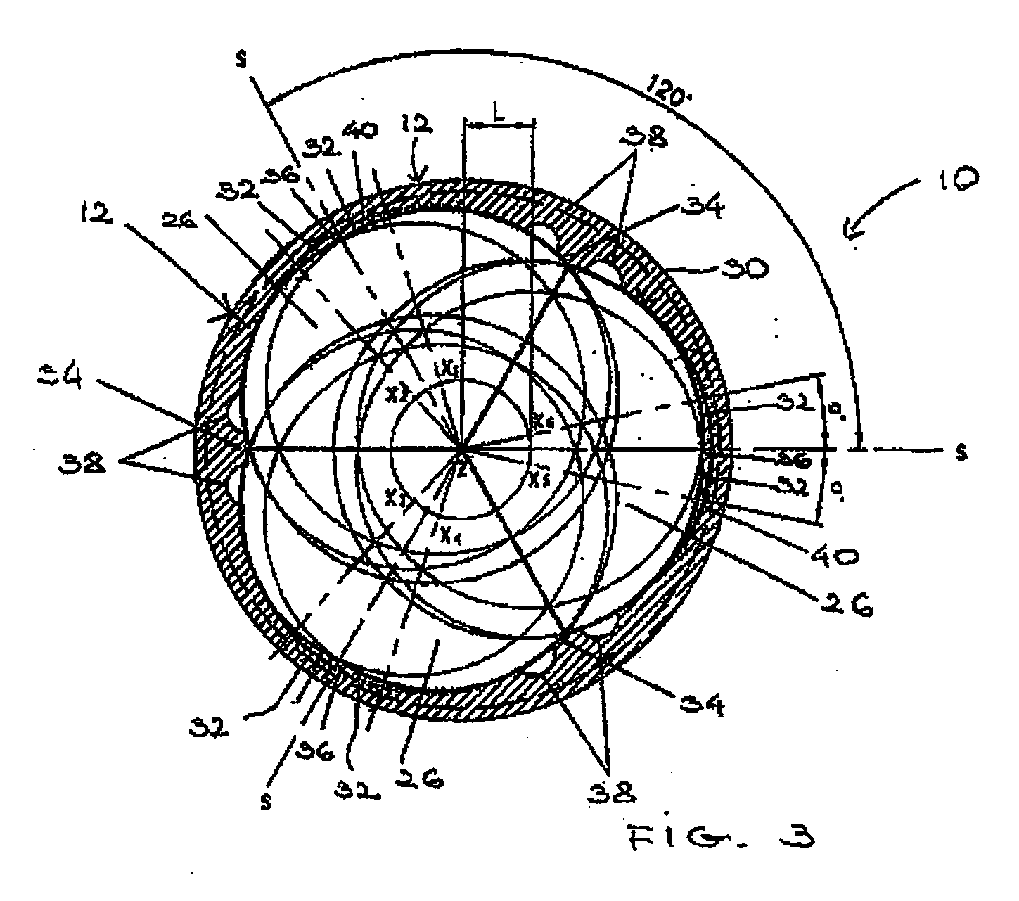
[0024]Shown in FIG. 1 is heart valve prosthesis 10, which includes annulus 12, housing closing element 14. Annulus 12 has a central axis, annulus axis Z, and an outer surface 16 with an outer diameter referred to herein as annulus diameter D. Preferably, at least a port...


PUM


Abstract

A heart valve prosthesis includes an annulus and a closing element having three leaflets. Hinge mechanisms are provided for attaching each leaflet to a top region of an interior surface of the annulus. In one example, the leaflets have convexo-concave surfaces and a non-uniform thickness. In another example, the top region of the interior surface has two sets of ledges which can be formed by intersecting three pairs of cylindrical surfaces. Ledges within each set are evenly spaced about the interior surface, a ledge in one set alternating with a ledge in the other set. In a further example, a bottom region of the interior surface is formed by intersecting three cylindrical surfaces.

Description

RELATED APPLICATIONS[0001]This application claims the benefit of Russian Patent Application No. 2006110832, filed on Apr. 4, 2006, the contents of which are incorporated herein by reference in their entirety.BACKGROUND OF THE INVENTION[0002]One type of artificial heart valves is the mechanical heart valve, generally manufactured from artificial materials such as titanium, titanium alloys, graphite and others.[0003]In a common design, mechanical heart valves include two leaflets held in a casing by hinges. When open, the blood flow through a bi-leaflet valve forms a central stream, between the two leaflets and two side streams. Deficiencies associated with bi-leaflet designs include turbulence, velocity gradients, non-synchronous opening of the leaflets and recirculation of the blood resulting in an increased burden on the heart.[0004]Tri-leaflets designs also have been developed. Known in the art, for instance, is a heart valve having flat leaflets as disclosed in U.S. Pat. No. 5,20...

Claims


Application Information

Patent Timeline
IPC IPC(8): A61F2/24
CPCA61F2/2403
Inventor SAMKOV, ALEXANDER
Owner SAMKOV ALEXANDER
Learn More