Method and system for finding a tool center point for a robot using an external camera

a robot and camera technology, applied in the field of method and system for finding the center point of the robot using the camera, can solve the problems of increasing the complexity of the automated system and the need for a higher-level type of programming

Inactive Publication Date: 2009-05-07
RIMROCK AUTOMATION
View PDF11 Cites 129 Cited by
  • Summary
  • Abstract
  • Description
  • Claims
  • Application Information

AI Technical Summary

Benefits of technology

[0003]An embodiment of the present invention may comprise a method for vision-based calibration of a tool-frame for a tool attached to a robot using a camera comprising: providing the robot, the robot having a wrist that is moveable, the robot having a control system that moves the robot and the wrist into different poses, the tool attached to the robot being at different orientations for the different poses, the robot control system defining a wrist-frame for the wrist of the robot such that the robot control system knows a position and an orientation of the wrist for the different poses via a kinematic model of the robot; providing the camera, the camera being mounted external of the robot, the camera capturing an image of the tool; designating a point on the tool in the image of the tool as an image tool center point of the tool, the image tool center point being a point on the tool that is desired to be an origin of the tool-frame for the kinematic model of the robot; moving the robot into a plurality of wrist poses, each wrist pose of the plurality of wrist poses being constrained such that the image tool center point of the tool is located within a specified geometric constraint in the image captured by the camera; calculating a tool-frame tool center point relative to the wrist-frame of the wrist of the robot for the tool as a function of the specified geometric constraint and also as a function of the position and the orientation of the wrist of the robot for each wrist pose of the plurality of wrist poses; defining the tool-frame of the tool relative to the wrist-frame for the kinematic model of the robot as the tool-frame tool center point; and, operating the robot to perform desired tasks with the tool using the kinematic model of the robot with the defined tool-frame.

Problems solved by technology

However, as the complexity of automated systems increased, so did the need for a higher-level type of programming.

Method used


Image

  • Method and system for finding a tool center point for a robot using an external camera
  • Method and system for finding a tool center point for a robot using an external camera
  • Method and system for finding a tool center point for a robot using an external camera

Examples


Embodiment Construction

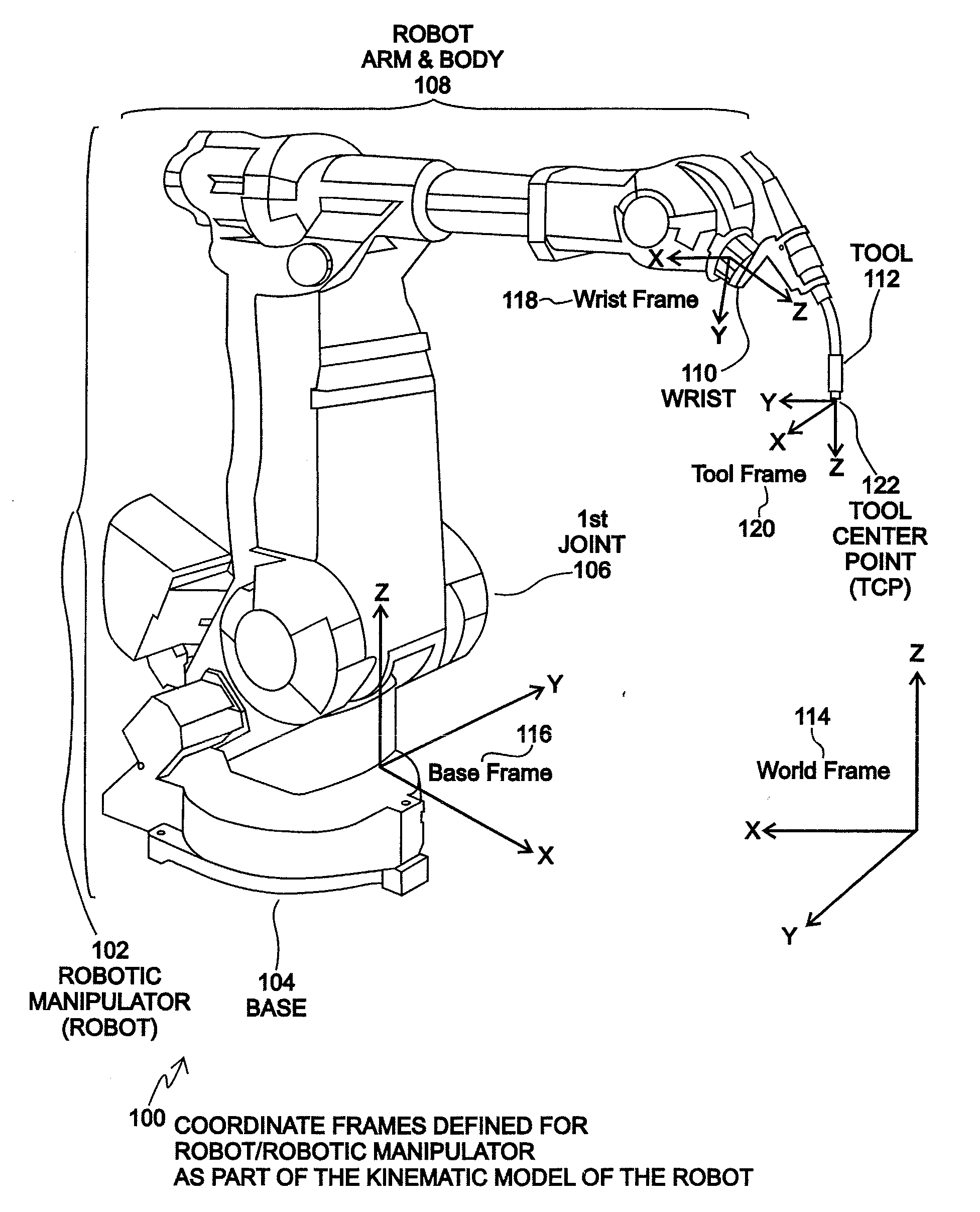
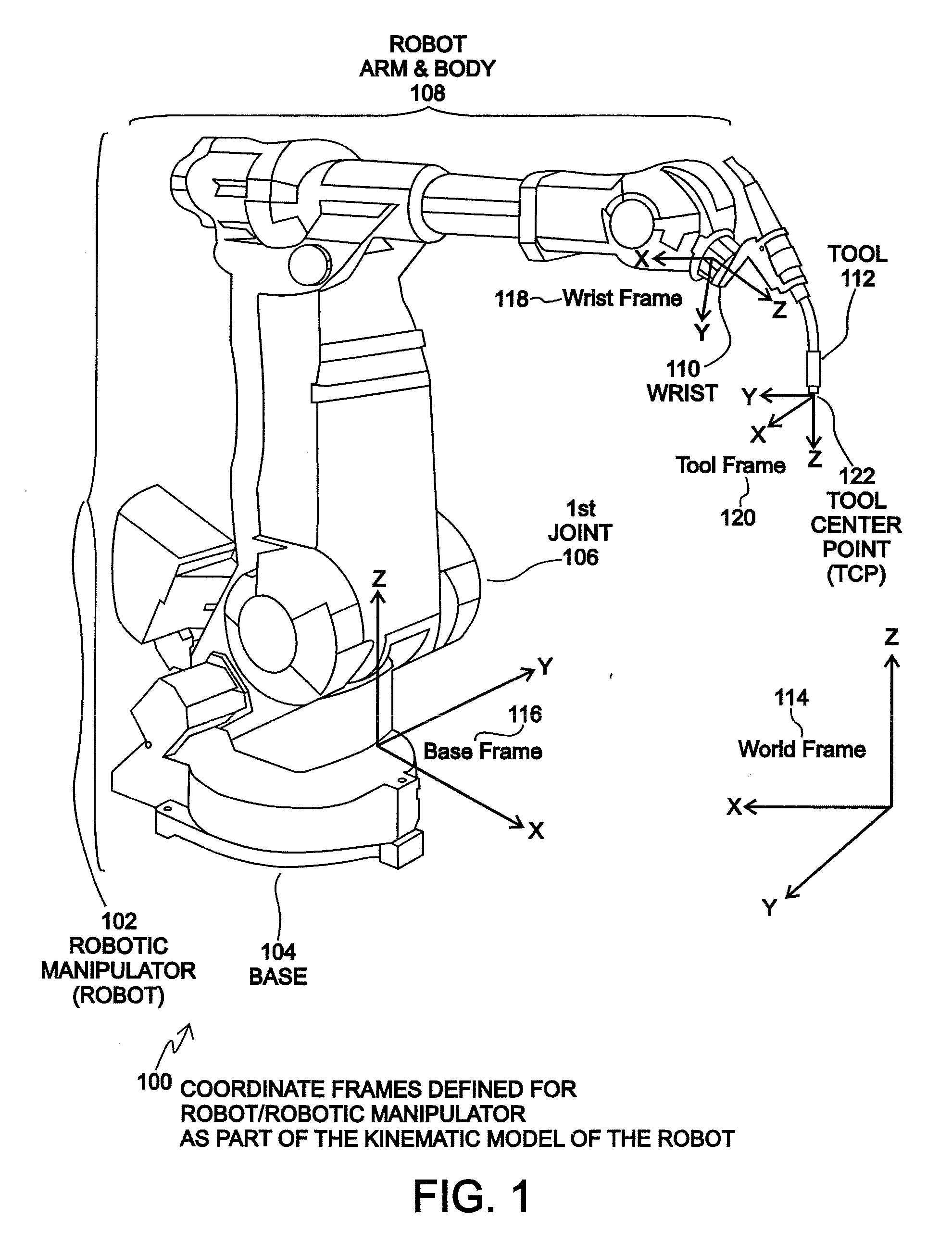
[0033]FIG. 1 is an illustration 100 of coordinate frames 114-120 defined for a robot / robot manipulator 102 as part of a kinematic model of the robot 102. In a simple form, an industrial robot may be comprised of a robot manipulator 102, power supply, and controllers. Since the power supply and controllers of a robot are not typically illustrated as part of the mechanical assembly of the robot, the robot and robot manipulator 102 are often referred to as the same object since the most recognizable part of a robot is the robot manipulator 102. The robot manipulator is typically made up of two sub-sections, the body and arm 108 and the wrist 110. A tool 112 used by a robot 102 to perform desired tasks is typically attached at the wrist 110 of the robot manipulator 102. A large number of industrial robots 102 are six-axis rotary joint arm type robots. The actual configuration of each robot 102 varies widely depending on the task the robot 102 is intended to perform, but the basic kinema...


PUM


Abstract

Disclosed is a method and system for finding a relationship between a tool-frame of a tool attached at a wrist of a robot and robot kinematics of the robot using an external camera. The position and orientation of the wrist of the robot define a wrist-frame for the robot that is known. The relationship of the tool-frame and/or the Tool Center Point (TCP) of the tool is initially unknown. For an embodiment, the camera captures an image of the tool. An appropriate point on the image is designated as the TCP of the tool. The robot is moved such that the wrist is placed into a plurality of poses. Each pose of the plurality of poses is constrained such that the TCP point on the image falls within a specified geometric constraint (e.g. a point or a line). A TCP of the tool relative to the wrist frame of the robot is calculated as a function of the specified geometric constraint and as a function of the position and orientation of the wrist for each pose of the plurality of poses. An embodiment may define the tool-frame relative to the wrist frame as the calculated TCP relative to the wrist frame. Other embodiments may further refine the calibration of the tool-frame to account for tool orientation and possibly for a tool operation direction. An embodiment may calibrate the camera using a simplified extrinsic technique that obtains the extrinsic parameters of the calibration, but not other calibration parameters.

Description

CROSS REFERENCE TO RELATED APPLICATIONS[0001]This application is based upon and claims priority to: U.S. provisional application Ser. No. 60 / 984,686, filed Nov. 1, 2007, entitled “A System and Method for Vision-Based Tool Calibration for Robots,” which is specifically incorporated herein by reference for all that it discloses and teaches.BACKGROUND OF THE INVENTION[0002]In the early days of using robots for automated manufacturing, robot tasks were programmed by manually teaching the robot where to go. While manufacturing tasks remained of the relatively simple pick-and-place type, this method of robot programming was adequate because the number of robot poses required was small. However, as the complexity of automated systems increased, so did the need for a higher-level type of programming. The concept of offline programming arose, which basically means that instead of manually recording joint angles for each desired position, a high level task description may be specified, and th...

Claims


Application Information

Patent Timeline
Patent Type & Authority Applications(United States)
IPC IPC(8): B25J13/08B25J19/04
CPCB25J9/1692G05B2219/39007G05B2219/40611G05B2219/40545G05B2219/39016
Inventor ELDRIDGE, BRYCECAREY, STEVEN G.GUYMON, LANCE F.
Owner RIMROCK AUTOMATION
Why Eureka
Try Eureka