Riser pan component for on-site waste systems

a waste system and septic tank technology, applied in the direction of building repairs, transportation and packaging, packaging, etc., can solve the problems of pvc pipe passageways, no means for accepting and retaining secondary concrete or other heavy materials septic tank covers, and even less secure arrangements

Inactive Publication Date: 2009-05-14
TWM IP LLC
View PDF80 Cites 9 Cited by
  • Summary
  • Abstract
  • Description
  • Claims
  • Application Information

AI Technical Summary

Problems solved by technology

There have been problems related to the use of make-shift access passage assemblies, such as modified chimney flues made of clay tile or cement, or extended lengths of large diameter pipe (such as smooth-walled PVC pipe, or corrugated or co-extruded pipe), used to form passageways between septic tanks and grade level.
However, such arrangements are considered even less secure than the stackable risers with injection-molded covers.
Further, the PVC pipe passageways, which typically have smooth inner walls, do not provide any means for accepting and retaining secondary concrete or other heavy material septic tank covers, either at or near grade level, or lower down in the passageway.
One difficulty relating to the use of concrete covers in the lid of the septic tank, especially in combination with such passageways formed by stackable risers, occurs when the concrete cover is cast in place in the concrete lid of the septic tank.
There is a tendency for there to be a mis-matched fit, which results in a locking wedge fit between the concrete cover and the complementary concrete ring, which is undesirable.
However, due to the relatively narrow width of the concrete ring within the concrete riser, there is some concern about degradation of the concrete seat for the concrete cover.
Over the years, repeated access to the septic tank via the concrete cover may tend to cause chips or cracks in the concrete seat, particularly if people accessing the tank drop the concrete cover in place from any significant height above the top of the septic tank, as is not uncommon due to both the weight of the concrete cover and the depth of some septic tanks.

Method used


Image

  • Riser pan component for on-site waste systems
  • Riser pan component for on-site waste systems
  • Riser pan component for on-site waste systems

Examples


first embodiment

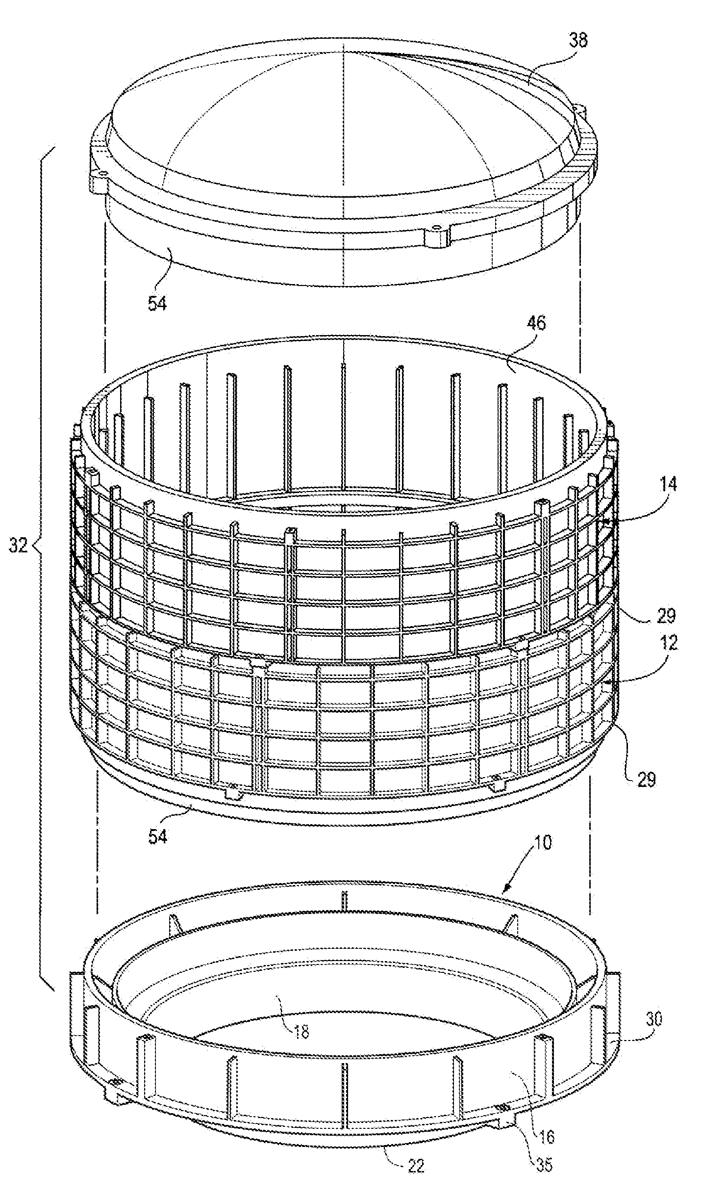
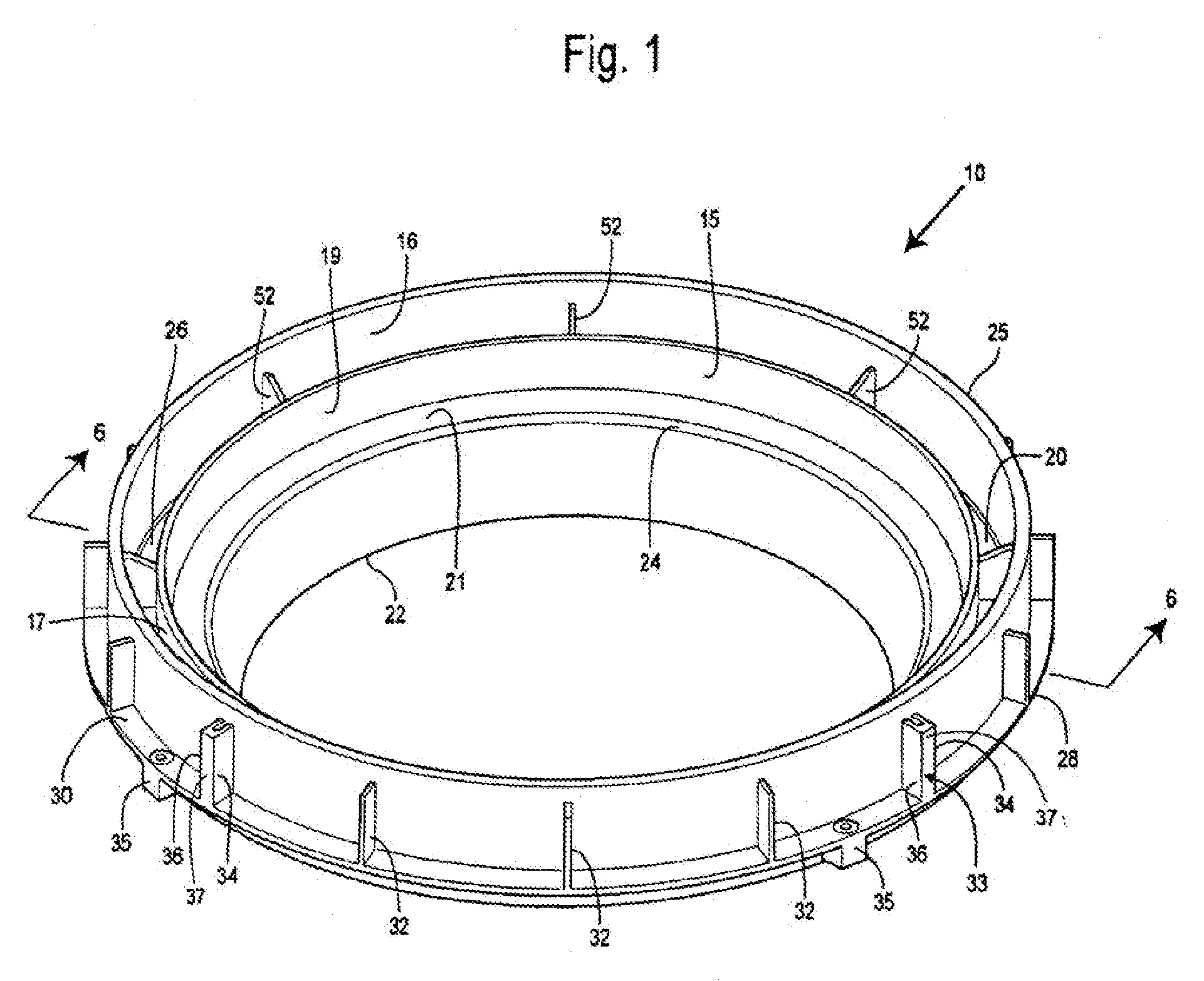
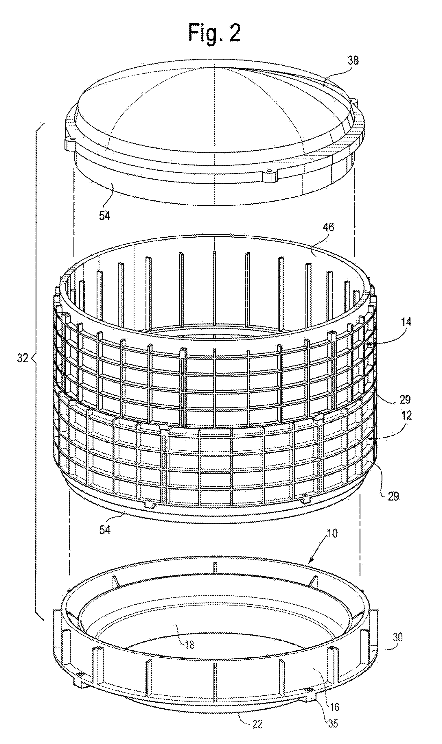
[0047]a riser pan 10 for use in conjunction with an access passageway formed of stackable, interconnecting risers 12, 14 is shown in FIGS. 1-10. In a preferred embodiment, the riser pan 10 takes the form of an injection-molded cylindrical member made of high density polyethylene. More specifically, the riser pan 10 includes an upper cylindrical wall 16, a lower pan portion 18, and an intermediate, generally flat annular ring 20. The pan portion 18 is preferably frustro-conical, has a lowermost edge 22 and an upper end 24. The frustro-conical pan portion 18 is tapered inwardly, such that its diameter at the lowermost edge 22 is less than at the upper end 24. In a preferred embodiment of the riser pan 10, the degree of taper of the pan portion 18 is in the range of between approximately 0° and 45°, and preferably about 14.796° for a 24″ riser pan, but those of ordinary skill in the art will appreciate that an even wider range of angles for the taper are possible, and even varying angl...

third embodiment

[0080]Like the riser pan 210 of the third embodiment, the riser pan 310 has at the lower end of the cylindrical sidewall 316 an interrupted annular ring 366, which is interrupted by a plurality of rib-receiving notches or gaps 368. An annular wall 372 may be provided axially outwardly of the interrupted annular ring 366, preferably as an integral extension of the sidewall 316. An inner sidewall 354 of an inverted channel is also provided axially inwardly of the interrupted annular ring 366.

[0081]The riser pan 310 further includes a plurality of vertically-oriented ribs 332, which in this embodiment are located on the interior of the cylindrical sidewall 316 of the riser pan 310. For purposes of nesting the riser pan 310 with other similar riser pans for shipping or storage, the rib-receiving notches or gaps 368 are sized to accommodate the vertically-oriented ribs 332 of a next-lower riser pan. Likewise, the vertical ribs 270 of a riser 214, such as on the riser shown in FIG. 17, fi...

fifth embodiment

[0085]The riser pan 510 includes gussets 552 and a generally flat annular ring 520 as in the fifth embodiment riser pan 410, described above, as well as other aspects shown in the drawing figures and described above with respect to previous embodiments, but not described in detail with respect to this embodiment for the sake of avoiding unnecessary repetition.

[0086]Like the standing circular rib 15 shown and described in the first embodiment riser pan 10, the downwardly-depending circular rib 515 of this sixth embodiment facilitates casting in place of a relatively thicker concrete cover (not shown). Inasmuch as many septic tank lids may have a thickness greater than the height of the frustro-conical pan portion 518, the circular rib 515 effectively increases the height available in which to cast a concrete cover without the concrete spilling over into the interior region of the riser pan 510 bounded by the upper cylindrical sidewall 516. The resulting concrete cover would have a tw...


PUM

PropertyMeasurementUnit
angleaaaaaaaaaa
angleaaaaaaaaaa
inner diameteraaaaaaaaaa

Abstract

An integrally formed riser pan member for use as a modular component within an access passageway for an on-site waste disposal system, such as a septic tank, to receivably retain a secondary cover member within, the riser pan member including a cylindrical body having an upper portion having a vertical wall member adapted to receive another modular passageway component thereon, and a lower portion which includes an integral pan portion to seatably receive a secondary cover member. The riser pan member further includes an annular ring between the upper and lower portions. The riser pan member can be employed as a lowermost, a highermost, or as an intermediate component in, for example, an access passageway formed of multiple stackable riser members. In addition, the riser pan member may be formed integrally with a stackable riser member.

Description

REFERENCE TO RELATED APPLICATIONS[0001]This application is a continuation of, and claims priority to, U.S. application Ser. No. 10 / 352,086, filed Jan. 28, 2003, and entitled “RISER PAN COMPONENT FOR ON-SITE WASTE SYSTEMS,” which is a regularly-filed application entitled to the benefit of the filing date of U.S. Provisional Application No. 60 / 353,620, filed Feb. 1, 2002. The entire specifications of both applications are hereby explicitly incorporated herein by reference.BACKGROUND[0002]1. Field of the Invention[0003]This disclosure relates generally to access covers for septic tanks and generally vertical access passageways between a septic tank (or another underground on-site waste disposal system or drainage collection system component) and grade level, and more specifically, to a component for use with (or without) a passageway formed by multiple stackable riser members, which component is capable of being cast into a concrete septic tank top, as well as being stackable with one ...

Claims


Application Information

Patent Timeline
Patent Type & Authority Applications(United States)
IPC IPC(8): E02D29/14B65D88/76E04H5/00E04C2/20E04B1/41E04B1/66B65D90/10E02D29/12E03F11/00
CPCE02D29/12E03F11/00E02D29/124E02D29/121
Inventor MEYERS, THEODORE W.
Owner TWM IP LLC
Why Eureka
Try Eureka