Method and apparatus for upgrading washing machine water efficiency

Inactive Publication Date: 2009-05-14
ILLINOIS TOOL WORKS INC
View PDF5 Cites 5 Cited by
  • Summary
  • Abstract
  • Description
  • Claims
  • Application Information

AI Technical Summary

Benefits of technology

[0010]The present invention provides a near “drop in” replacement for a mechanical water level control obtaining analog pressure information and water flow information to allow improved water conservation even for low-end washing machines. The invention employs a low cost microprocessor and power interface circuitry making it cost-effective for standard washing machine designs and provides direct

Problems solved by technology

Improved control of water usage to match the size of the load being washed can have a significant environmental benefit but this feature is not normally available on lower end washing mach

Method used


Image

  • Method and apparatus for upgrading washing machine water efficiency
  • Method and apparatus for upgrading washing machine water efficiency
  • Method and apparatus for upgrading washing machine water efficiency

Examples


Embodiment Construction

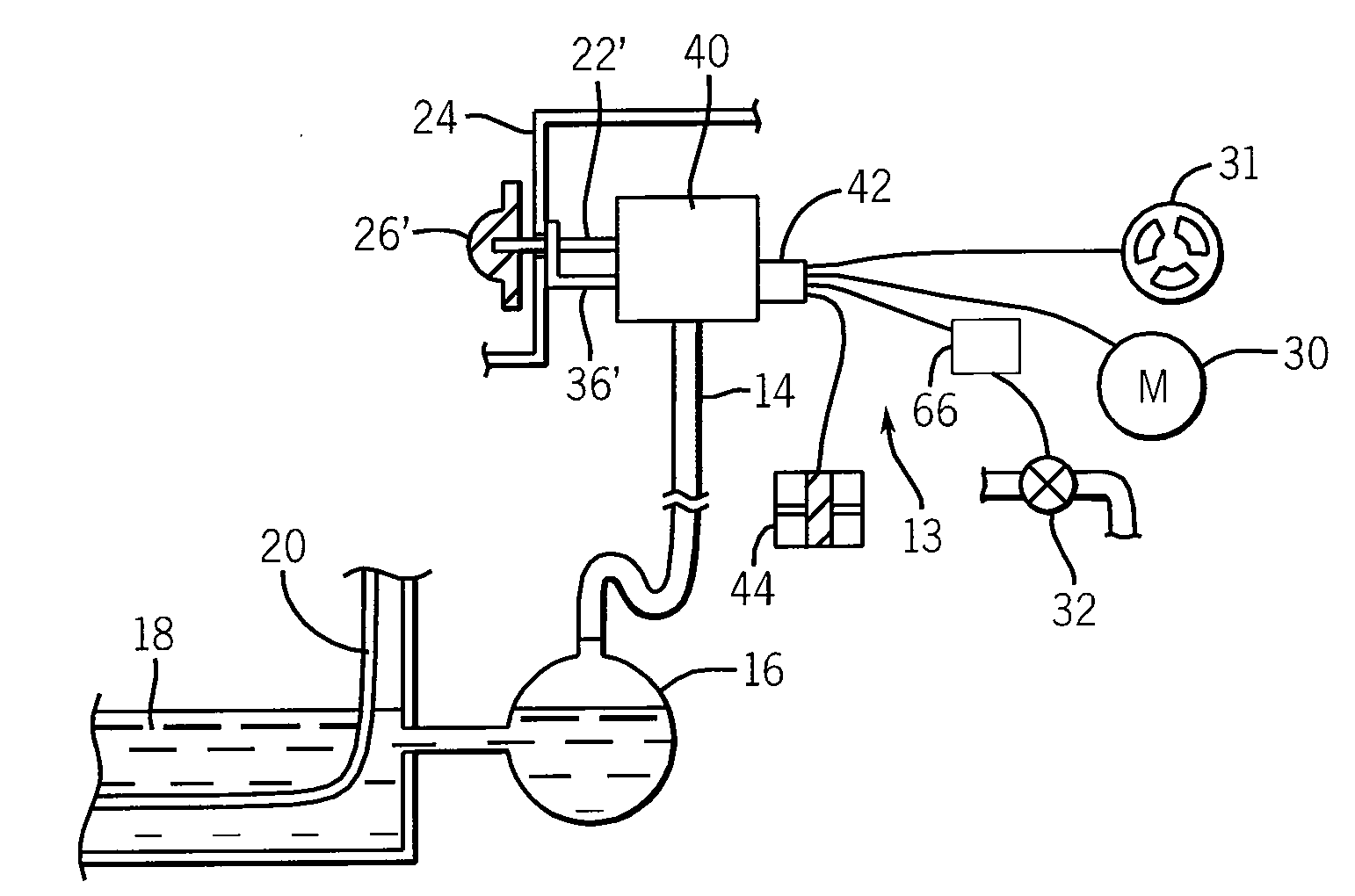
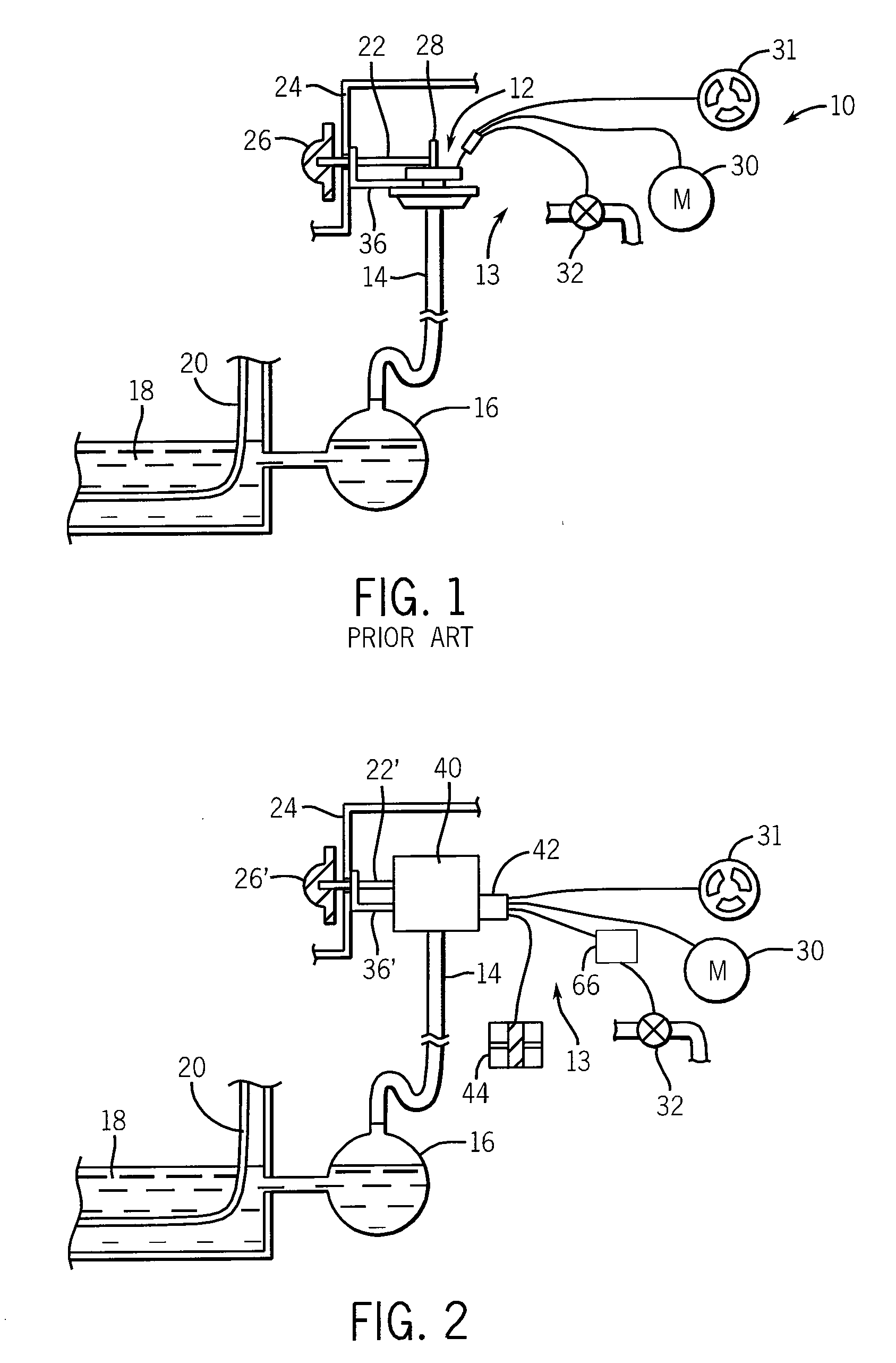
[0034]Referring now to FIG. 1, a prior art washing machine 10 may employ a mechanical water level control 12 of conventional design having an internal diaphragm (not shown) providing a pressure switch communicating on one side with a hose 14 connected to a pressure dome 16. Water 18 filling the wash tub 20 of the washing machine 10 flows into the pressure dome 16 compressing air at the top of the pressure dome 16 communicating to the pressure switch of the mechanical water level control 12 to move the diaphragm of the pressure switch upward (as oriented in FIG. 1) against the action of an internal spring (not shown).

[0035]The mechanical water level control 12 may have a shaft 22 passing through a console panel 24 to a rotary knob 26. The knob 26 may be rotated to set a water level by turning the shaft 22 which communicates with a cam 28 to change the compression of the internal spring on the diaphragm of the pressure switch of the mechanical water level control 12. Thus, different a...


PUM


Abstract

A water level control for a washing machine provides an integrated unit that may replace standard mechanical water level controls with a microprocessor-based circuit that may provide for more sophisticated water management in a standard washing machine using a non-microprocessor cycle timer.

Description

CROSS REFERENCE TO RELATED APPLICATION[0001]This Non-Provisional Application claims benefit to U.S. Provisional Application Ser. No. 60 / ______ filed 60 / 987,956 filed Nov. 14, 2007 and hereby incorporated by reference.FIELD OF THE INVENTION[0002]The present invention relates generally to controls for household appliances and, in particular, to a water height control for washing machines providing improved water efficiency for standard washing machines.BACKGROUND OF THE INVENTION[0003]The present invention relates to controls for household appliances and, in particular, to a water height control for washing machines providing improved water efficiency for standard washing machines.[0004]Conventional clothes washing machines provide for a tub for receiving clothing, water, and detergent and for providing agitation to clean clothing. The amount of water in the tub is typically controlled by a selector switch on the washing machine console. An electric valve is controlled to allow the tu...

Claims


Application Information

Patent Timeline
IPC IPC(8): D06F33/02
CPCD06F39/08D06F35/006D06F2101/00D06F2103/04
Inventor GILL, DAVID C.LARSON, ERIC K.BARRENA, JUAN J.ROMO, MARK A.
Owner ILLINOIS TOOL WORKS INC
Why Eureka
Try Eureka