
Intake Port Structure Internal Combustion Engine

Inactive Publication Date: 2009-05-14
TOYOTA JIDOSHA KK
View PDF5 Cites 6 Cited by
  • Summary
  • Abstract
  • Description
  • Claims
  • Application Information

AI Technical Summary

Benefits of technology

[0013]In view of the above, it is an object of the invention to provide an intake port structure for an internal combustion engine, which avoids the locling of an airflow control valve, which increases the strength of a swirling airflow generated in a combustion chamber, and which suppresses the deterioration of fuel efficiency and reduces emissions.

Problems solved by technology

The pivot movement of the airflow control valve is adversely affected by the deposit thus generated.
Further, the airflow control valve may be locked due to the deposit.
However, in Patent Publication 1, no consideration is given to the problem that the airflow control valve may be locked, and the problem that the fuel efficiency of the internal combustion engine may deteriorate, and the emissions may increase due to the oil adhering to the airflow control valve.

Method used


Image

  • Intake Port Structure  Internal Combustion Engine
  • Intake Port Structure  Internal Combustion Engine
  • Intake Port Structure  Internal Combustion Engine

Examples


Embodiment Construction

[0038]In the following description, the present invention will be described in more detail in terms of example embodiments.

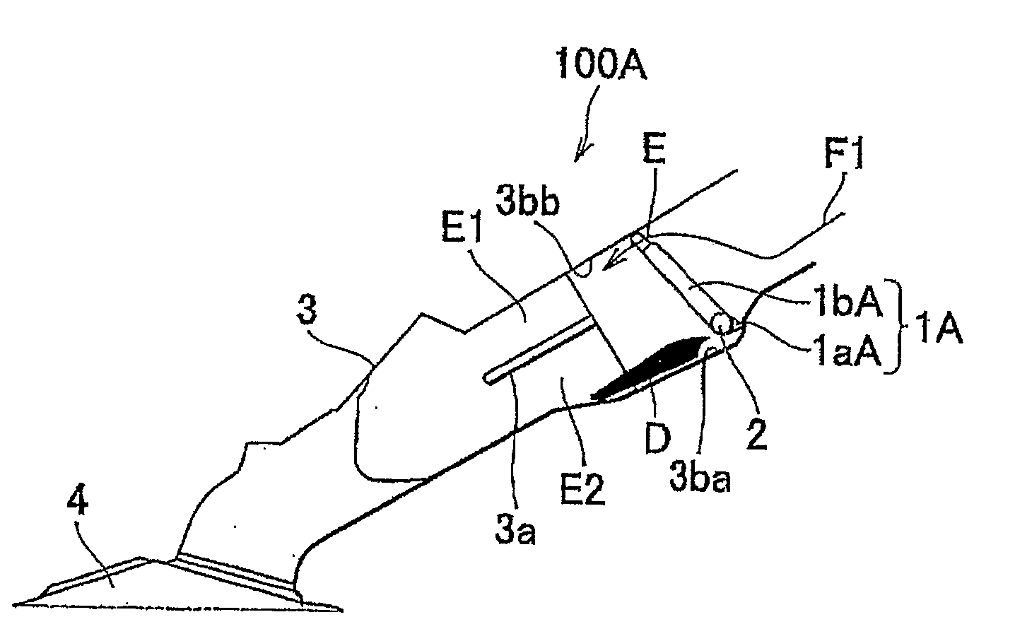
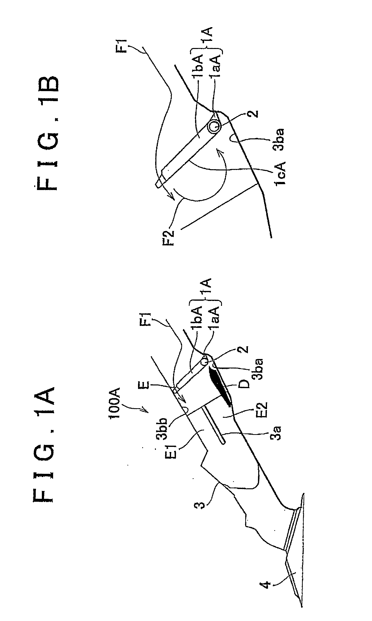
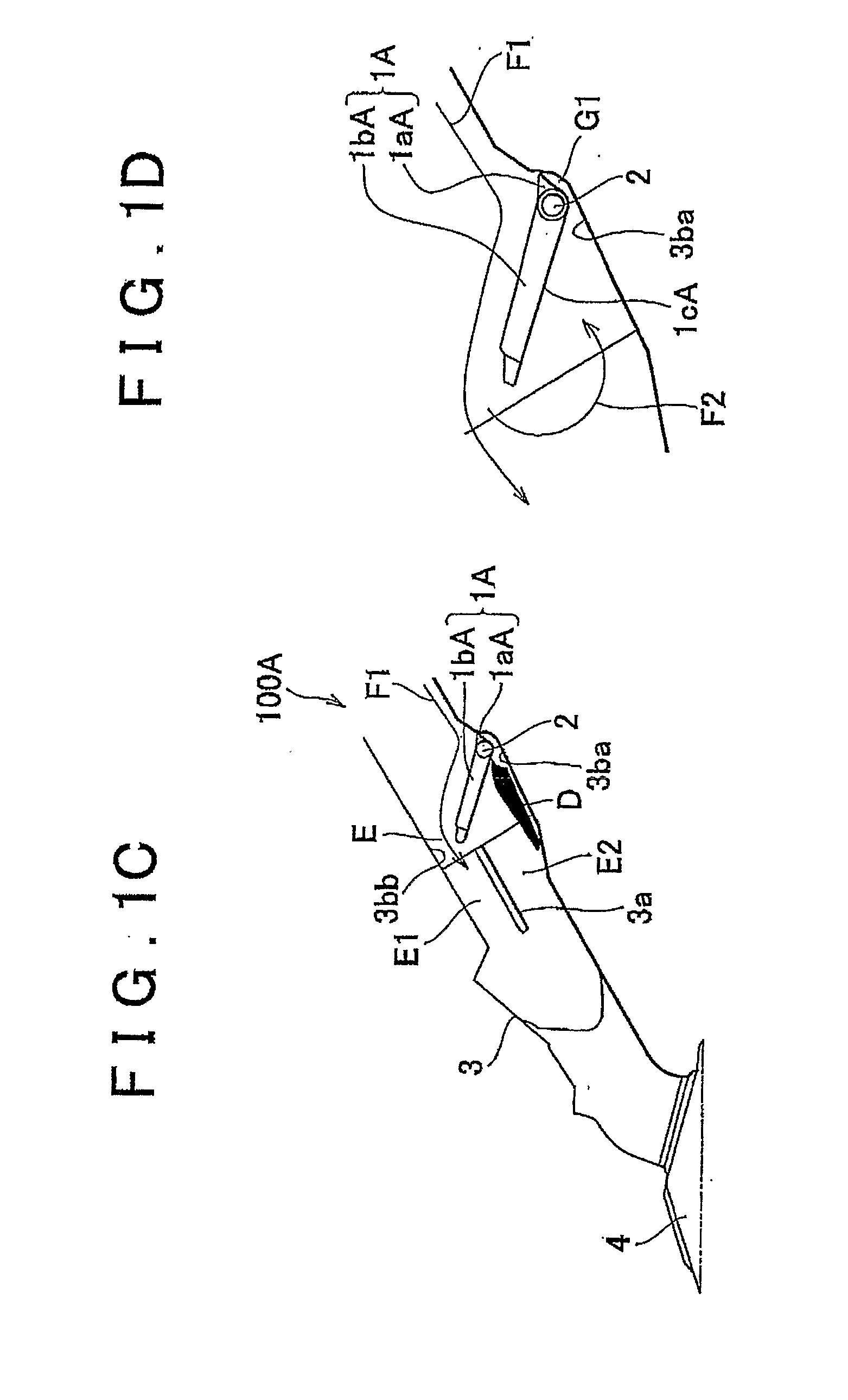
[0039]An intake port structure 10A according to a first embodiment of the invention will be described in detail with reference to FIG. 1A to FIG. 1F. FIG. 1A to FIG. 1F show the configuration of an intake port structure for an internal combustion engine (hereinafter, referred to simply as “intake port structure”) 100A according to this embodiment. More specifically, FIG. 1A shows that an airflow control valve 1A is completely closed. FIG. 1B is an enlarged view showing that the gap between the airflow control valve 1A and the wall surface 3ba of an intake port 3 is closed when the airflow control valve 1A is completely closed. FIG. 1C shows that the airflow control valve 1A is partly opened. FIG. 1D is an enlarged view showing that the gap between the airflow control valve 1A and the wall surface 3ba is closed when the airflow control valve 1A is partly opened. ...


PUM


Abstract

An intake port structure for an internal combustion engine according to the invention includes a valve shaft provided in an intake port; and an airflow control valve that is supported by the valve shaft at one end of the airflow control valve or at a position near the one end. A gap is formed between the airflow control valve and a wall surface of the intake port, which is positioned on one side of the valve shaft. Because intake airflow passes through the gap that is formed, the generation of a deposit is suppressed, and the locking of the airflow control valve is avoided.

Description

BACKGROUND OF THE INVENTION[0001]1. Field of the Invention[0002]The invention relates to an intake port structure for an internal combustion engine. More particularly, the invention relates to an intake port structure for an internal combustion engine, which avoids the locking of an airflow control valve, which increases the strength of a swirling airflow generated in a combustion chamber, and which suppresses the deterioration of fuel efficiency and reduces emissions.[0003]2. Description of the Related Art[0004]As a technology related to the invention, an intake port structure for an internal combustion engine is known. In the intake port structure, an airflow control valve provided in an intake port is controlled to be opened / closed to control the flow of intake air, and to generate a swirling flow such as a tumble flow and a swirl in a combustion chamber. The swirling airflow, such as the tumble flow and the swirl, promotes the mixing of fuel and air, and the transmission of flam...

Claims


Application Information

Patent Timeline
IPC IPC(8): F02M35/104
CPCF02B31/06F02B2275/48F02D9/1025Y02T10/146F02D9/1055Y02T10/125F02D9/103Y02T10/12
Inventor ABE, KAZUYOSHIWAKABAYASHI, SHINYA
Owner TOYOTA JIDOSHA KK
Learn More