Check patentability & draft patents in minutes with Patsnap Eureka AI!

Control unit for lift system for coverings for architectural openings

a technology of control unit and architectural opening, which is applied in the direction of shutters/movable grilles, door/window protective devices, wing arrangements, etc., can solve the problems of physical harm to infants and young children

Inactive Publication Date: 2009-05-14
HUNTER DOUGLAS INC
View PDF8 Cites 41 Cited by
  • Summary
  • Abstract
  • Description
  • Claims
  • Application Information

AI Technical Summary

Benefits of technology

[0011]The brake assembly in the aforenoted embodiment includes the driven gear and a driven shaft on which it is mounted for unitary rotation. The driven shaft is, in turn, operatively connected to a lift shaft for the covering, which includes lift cords for raising or lowering the covering in a conventional manner. Accordingly, when the driven shaft is rotated, so are the lift shaft and a lift system within a head rail of the covering. A one-way brake in the brake assembly selectively prevents the drive shaft from rotating when it is not being driven by the drive assembly and therefore retains the covering at any selected degree of retraction within the architectural opening. A release system, however, is operatively associated with the driven shaft and allows the driven shaft to rotate in an opposite direction when the one-way brake is released. The release system includes a governor and a gear train operatively connected to the driven shaft so that if the governor is prevented from rotating the driven shaft is also prevented from rotating in the afore noted opposite direction. The release system, however, is operative to selectively permit rotation of the governor, which in turn permits rotation of the driven shaft in the aforenoted opposite direction, which thereby allows the covering to drop by gravity from any degree of retraction.
[0013]Pursuant to the above, the control unit has a pull cord operated drive assembly for rotating a driven shaft in a single direction with the pull cord also being operative on a one-way brake for selectively preventing rotation of the driven shaft in an opposite direction. In this manner the covering can be raised or lowered to any desired degree.

Problems solved by technology

Loops of this type have presented problems in inadvertently causing physical harm to infants and young children who may catch a body part within the loop.

Method used


Image

  • Control unit for lift system for coverings for architectural openings
  • Control unit for lift system for coverings for architectural openings
  • Control unit for lift system for coverings for architectural openings

Examples


first embodiment

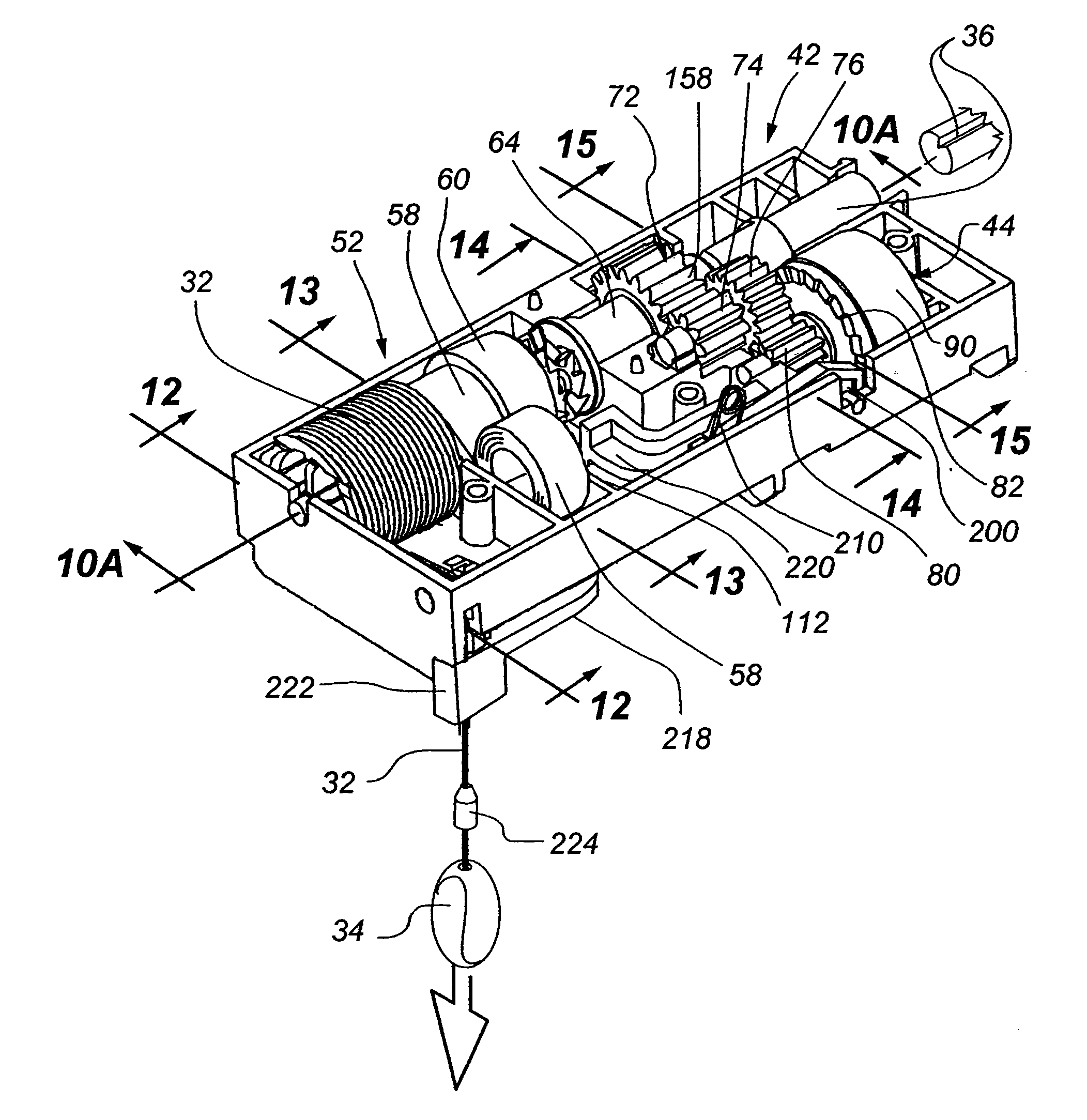
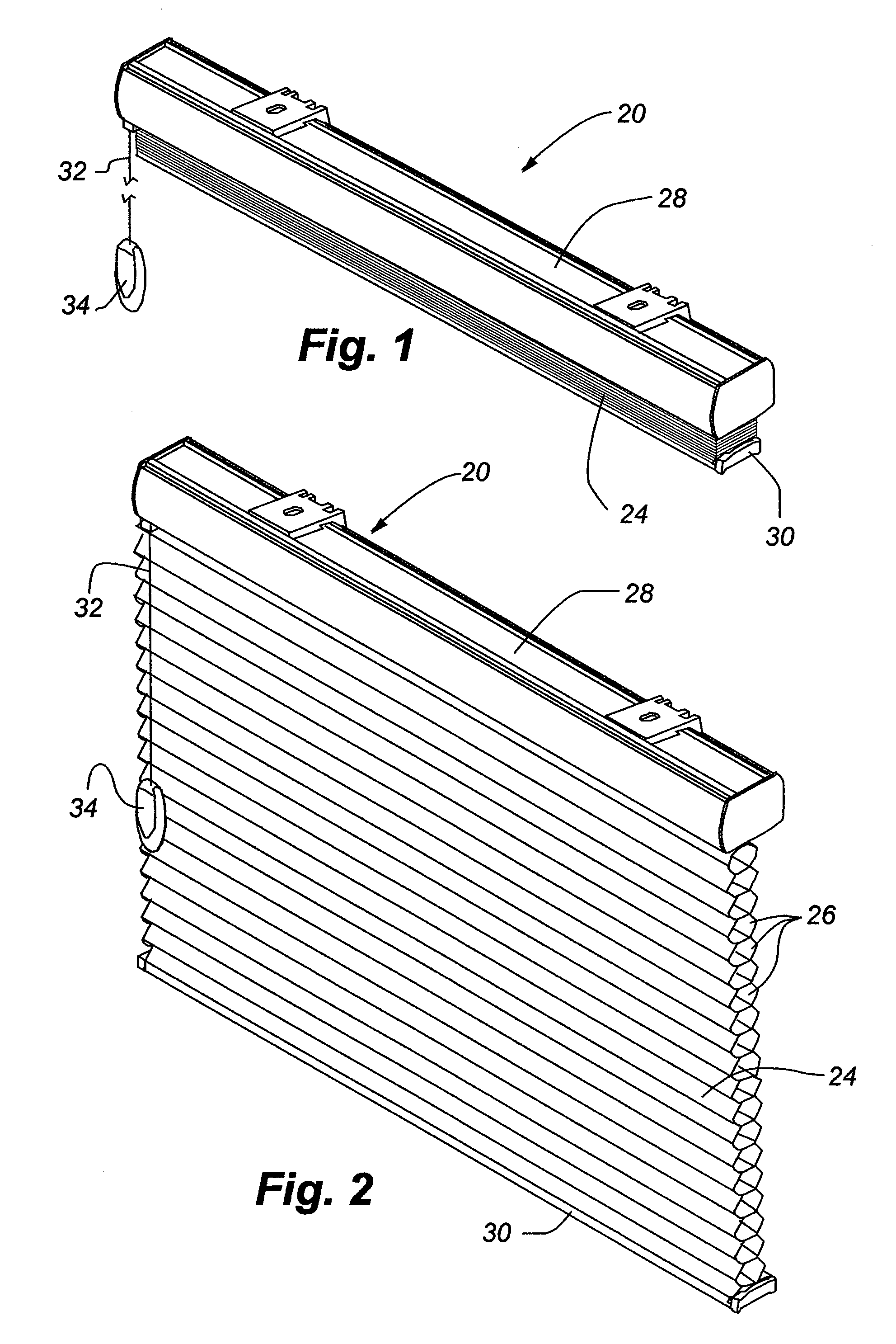
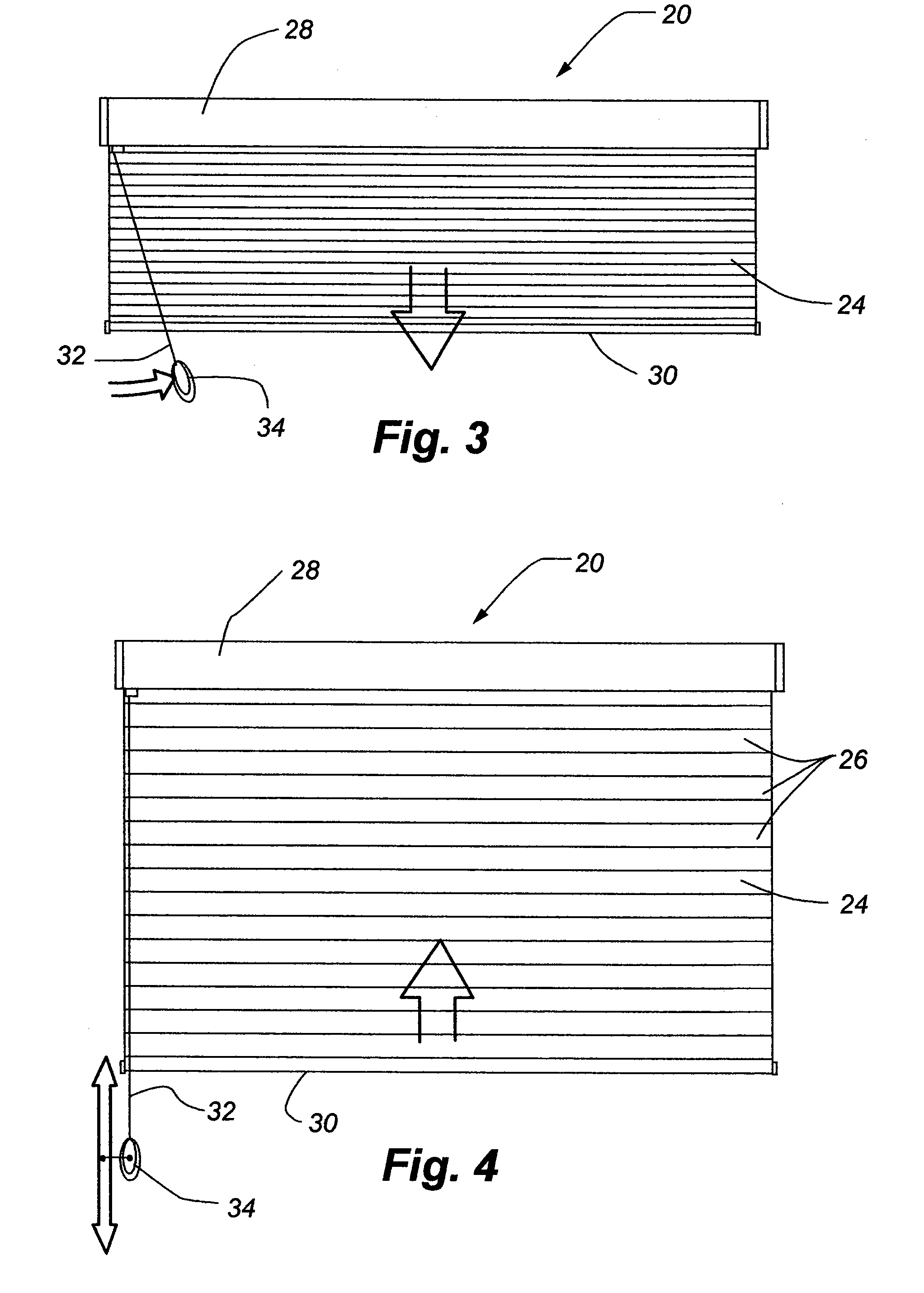
[0056]A covering 20 for an architectural opening (not shown) incorporating a control unit 22 in accordance with the present invention is illustrated in FIGS. 1 through 4. It is to be appreciated the covering illustrated is for exemplary purposes only as the control unit would be useful with various types of retractable coverings found in architectural openings. In the covering illustrated, a cellular shade material 24 having horizontally disposed interconnected transversely collapsible cells 26 is suspended from a head rail 28 by a lift system with a weighted bottom rail 30 being secured along the lower edge of the shade material. The covering is of the retractable type so that it can be fully extended as shown in FIG. 2, fully retracted as shown in FIG. 1 or partially extended to any degree between the fully extended and retracted positions. As will be appreciated with the description of the control unit hereafter, it is operated with a single pull cord 32 having a tassel 34 on a l...

second embodiment

[0092]The drive assembly 250 of the second embodiment is probably best appreciated by reference to FIGS. 18-20. It will there be seen the drive assembly includes a cord spool 260 about which the pull cord 262 can be wrapped and unwrapped with the cord spool having a cylindrical drum 264 at one end with an integral circumferential gear 266 thereon. The opposite end of the cord spool from the circumferential gear is beveled at 268 so as to retain the pull cord on a cylindrical wrap surface 270 of the cord spool when it is wrapped therearound. The bevel facilitates unwrapping and wrapping of the pull cord about the cord spool in a controlled manner. The cord spool is biased in a wrapping direction by a biasing spring 271 to be described later.

[0093]Extending axially away from the gear 266 of the cord spool 260 is a support shaft 272 having first 274, second 276, third 278 and fourth 280 axially contiguous segments of respectively diminishing diameter that are coaxial with the cylindric...


PUM


Abstract

A control unit for controlling a lift system in a covering for an architectural opening includes a drive assembly and a brake assembly. The drive assembly includes a spool about which a pull cord can be wrapped or unwrapped and a spring for biasing the spool in a direction to wrap the pull cord thereabout. A drive gear is operatively associated with the spool so that upon a pulling of the pull cord and unwrapping of the cord from the spool, the drive gear is shifted axially into engagement with a driven gear in the brake assembly. The driven gear under such circumstances rotates a driven shaft, which in turn rotates a lift shaft in the covering to raise the covering from an extended position to a retracted position.

Description

CROSS-REFERENCE TO RELATED APPLICATION[0001]The present application claims benefit under 35 U.S.C. §119(e) to U.S. Provisional Patent Application No. 60 / 987,861, which was filed on Nov. 14, 2007 and entitled “Control Unit For Lift System For Coverings For Architectural Openings”, which is incorporated by reference into the present application in its entirety.BACKGROUND OF THE INVENTION[0002]1. Field of the Invention[0003]The present invention relates generally to control systems for operating retractable coverings for architectural openings and more particularly to a unit having a uni-directional drive assembly wherein the covering can be incrementally raised upon repeated reciprocating pull motions on a pull cord and a brake assembly operatively associated with the drive assembly wherein the brake assembly selectively prevents the shade from dropping by gravity.[0004]2. Description of the Relevant Art[0005]Coverings for architectural openings such as windows, doors, archways and th...

Claims


Application Information

Patent Timeline
Patent Type & Authority Applications(United States)
IPC IPC(8): E06B9/24
CPCE06B2009/3222E06B9/322E06B9/24
Inventor LESPERANCE, LEO J.
Owner HUNTER DOUGLAS INC
Features
  • R&D
  • Intellectual Property
  • Life Sciences
  • Materials
  • Tech Scout
  • Unparalleled Data Quality
  • Higher Quality Content
  • 60% Fewer Hallucinations
Learn More