Variable heat flux heat exchangers

a heat exchanger and variable heat flux technology, applied in the field of heat exchangers, can solve the problems of poor temperature control or oversized heat exchangers, the cooling power in one zone cannot be altered, and the reaction may progress too slowly and too quickly, and achieve the effect of uniform temperature profiles and ready-to-adap

Inactive Publication Date: 2009-05-14
ASHE MORRIS LTD
View PDF6 Cites 77 Cited by
  • Summary
  • Abstract
  • Description
  • Claims
  • Application Information

AI Technical Summary

Benefits of technology

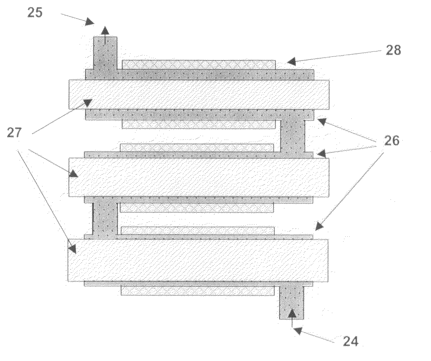
[0009]In a preferred embodiment the present disclosure provides a flexible heat exchange system which can be readily adapted in order to satisfy the needs of different flowing regimes and their heat exchange requirements. For example the exchanger may consist of a collection of plates and spacers of different sizes which can be assembled, dismantled and reassembled to provide different systems involving a process conduit of varying cross section as desired for the particular process that is being performed. In this way it is possible to provide reaction systems which have the flexibility to be used for a wide range of reactions with minimal modification of the apparatus employed.
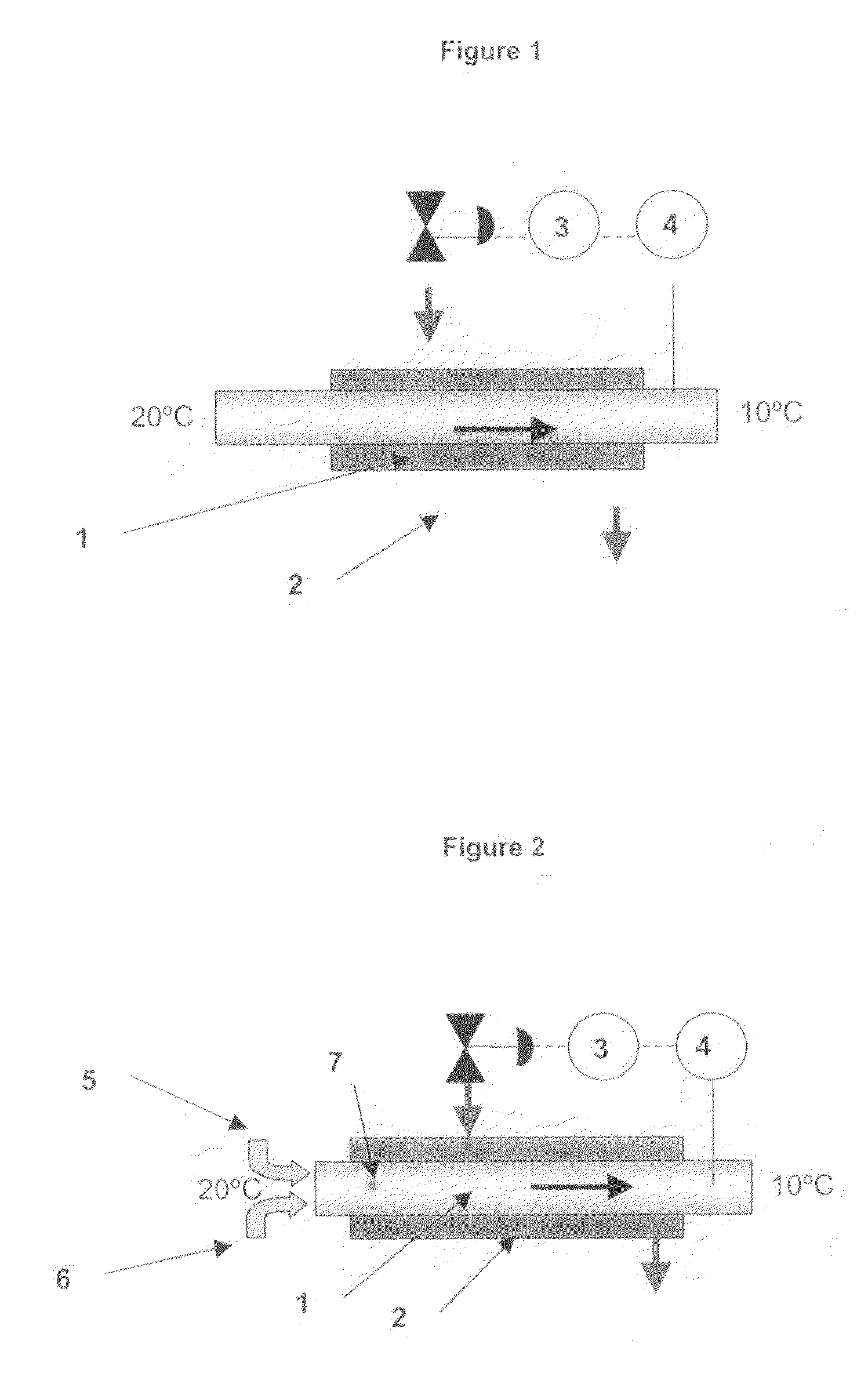
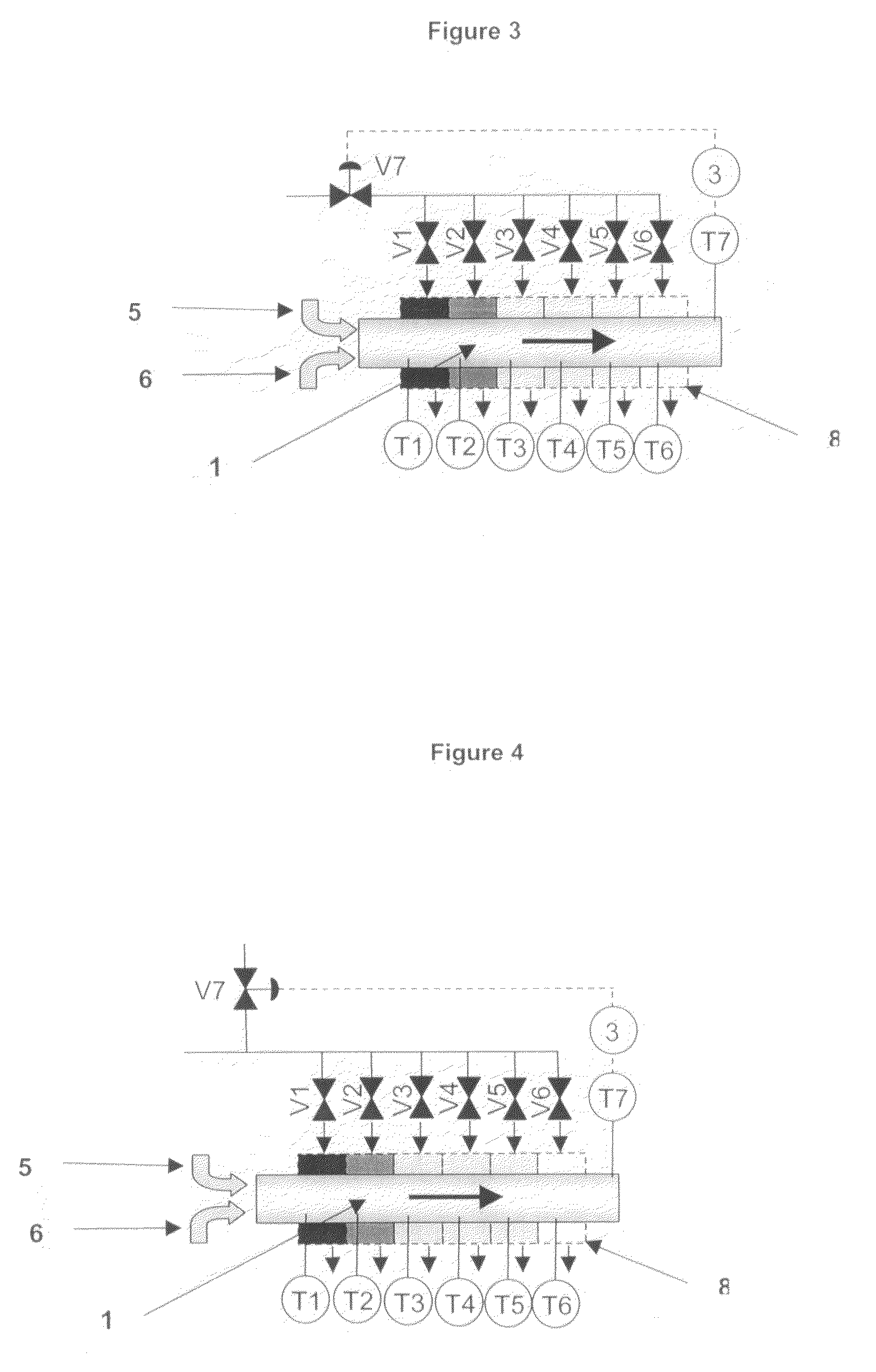
[0010]Accordingly, the present disclosure provides an improved method of designing and using heat exchangers where the heat transfer surface is broken up into multiple separate heat transfer elements and each element can be independently set or controlled. This is done so as to achieve more uniform temperature profiles throughout the heat exchanger where processes are liberating or absorbing heat. It is also used to create non uniform temperature profiles where these are required. The technique is also used where a combination of heating and cooling within the same heat exchanger is required. The technique can be used to initiate strong exotherms on the cooling surface. The technique is also used to vary the strength of heating or cooling within a heat exchanger where the tolerance to heating or cooling changes by virtue of chemical or physical changes within the product.

Problems solved by technology

The disadvantage with this is that the cooling power in one zone cannot be altered without changing the cooling power in all the other zones.
This can be undesirable because it can overcool and stall the reaction (or even freeze the product in the heat exchanger).
Excessive heating or cooling in some zones can lead to a variety of problems as undesirable temperatures, burning, boiling freezing or fouling.
Conversely, insufficient heating or cooling in some areas can lead to poor temperature control or oversized heat exchangers.
Also, some reactions are temperature sensitive and if the temperature is wrong, the reaction may progress too slowly, too quickly or the wrong reaction may take place.
In the case of exothermic and endothermic reactions, localised temperature overshoots within the exchanger are sometimes tolerated (even though they may not be desirable).
In some systems, a high (heat transfer) surface area / volume heat exchangers may be used however these operate with higher pressure drops and have an increased tendency to block.
The disadvantage with this method is that the right level of heating or cooling in one part of the heat exchanger may be too much in another.

Method used


Image

  • Variable heat flux heat exchangers
  • Variable heat flux heat exchangers
  • Variable heat flux heat exchangers

Examples


Embodiment Construction

[0034]In this document, the material which is required to be heated or cooled within the heat exchanger is referred to as the ‘process material’. The process material may be a liquid, an emulsion, a super critical fluid, a vapour, a gas, a paste, solid particulates or a combination of these.

[0035]The phrase ‘process conduit’ refers to the space (such as channel, pipe, gap between plates etc) through which the process material flows.

[0036]The phrase ‘process conduit area’ refers to the cross-sectional area of the aperture through which the process material flows at a given point.

[0037]In this document, the phrase ‘uniform flow’ is used to describe a velocity profile of the process material passing through the process conduit (in a laminar or turbulent fashion) which is substantially constant across the face of the process conduit. It also implies that there are no pockets or dead spaces within the process conduit. The term ‘substantially’ is used because some variation in velocity wi...


PUM


Abstract

A system for heat exchange is provided in which process material flows through a heat exchanger comprising multiple heat transfer stages and the heating and or cooling power applied to each stage can be modified independently. The system comprises a unitary heat exchanger comprising a heat transfer surface comprising a plurality of elements or zones over which a process material can flow wherein each element or zone has independent means to set or control the level of heating or cooling within that zone.

Description

BACKGROUND[0001]1. Field of the Disclosure[0002]This present disclosure relates to heat exchangers where the process material flows over a heat transfer surface. Typical examples include plate heat exchangers, shell and tube heat exchangers, drilled block heat exchangers, jacketed tanks, jacketed pipes, vessels with internal coils etc.[0003]The disclosure is particularly concerned with heat exchangers used for heating or cooling (or both) flowing materials where conditions change as the process material progresses through the heat exchanger (such as chemical reactions, polymerisation reactions, crystallisation, condensation, gas cooling etc). For example many chemical reactions are exothermic and have a rate of reaction which decays with time. Thus as a reacting fluid progresses through the heat exchanger, the rate of heat liberation also declines and hence requires less cooling (per unit volume of process fluid) if the process fluid is to be held at constant temperature. The disclo...

Claims


Application Information

Patent Timeline
Patent Type & Authority Applications(United States)
IPC IPC(8): F28F1/10F28D9/00F28F13/08F28F27/02
CPCB01J19/0013B01J19/2415B01J19/249B01J2219/00015B01J2219/00063B01J2219/00094B01J2219/00159B01J2219/00202B01J2219/00211B01J2219/00238B01J2219/2453B01J2219/2458B01J2219/2462B01J2219/2464B01J2219/2479B01J2219/2481B01J2219/2485B01J2219/2486B01J2219/2488B01J2219/2493F28D9/0093F28D2021/0022F28F13/08F28F27/02
Inventor ASHE, ROBERT
Owner ASHE MORRIS LTD
Why Eureka
Try Eureka