Cosmetic receptacle

a receptacle and cosmetic technology, applied in the field of cosmetic receptacles, can solve the problems of inconvenient operation, inability to maintain the initial assembling state of the button b>140/b> and the pumping part b>150/b>, and achieve the effect of preventing cosmetic leakage through the discharging channel and simple outer receptacle structur

Inactive Publication Date: 2009-05-14
TAESUNG IND
View PDF7 Cites 56 Cited by
  • Summary
  • Abstract
  • Description
  • Claims
  • Application Information

AI Technical Summary

Benefits of technology

[0077]Herein, so as to make the structure of the outer receptacle simple, it is preferable that the outer receptacle includes an outer receptacle body part having a pipe-shape and a locking ring coupled with an inner surface of an upper end of the outer receptacle body part so as to rotate together with the outer receptacle body part, and the stopper protuberance is formed at an inner surf

Problems solved by technology

As such, since the inner receptacle 112 is elevated together with the button 140, there is also another problem in that an initial

Method used


Image

  • Cosmetic receptacle
  • Cosmetic receptacle
  • Cosmetic receptacle

Examples


Embodiment Construction

[0087]Hereinafter, the present invention will be described with reference to the following drawings.

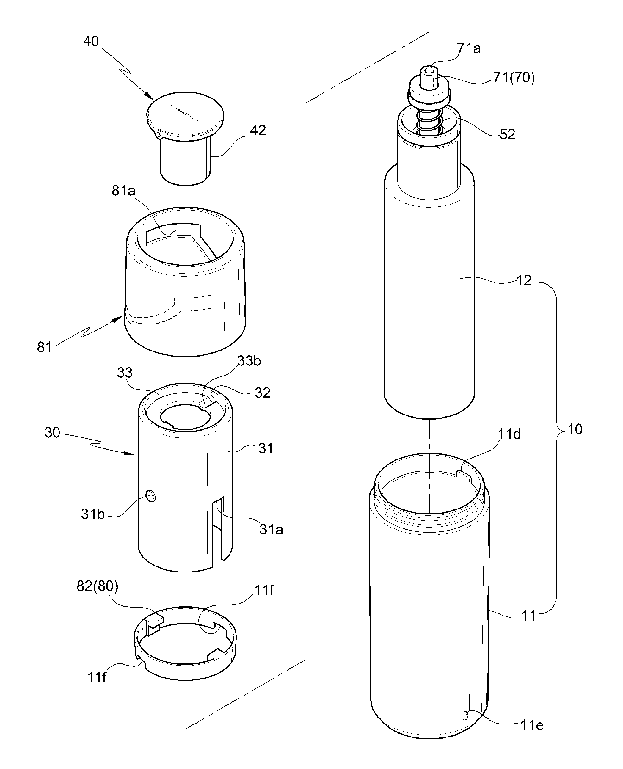
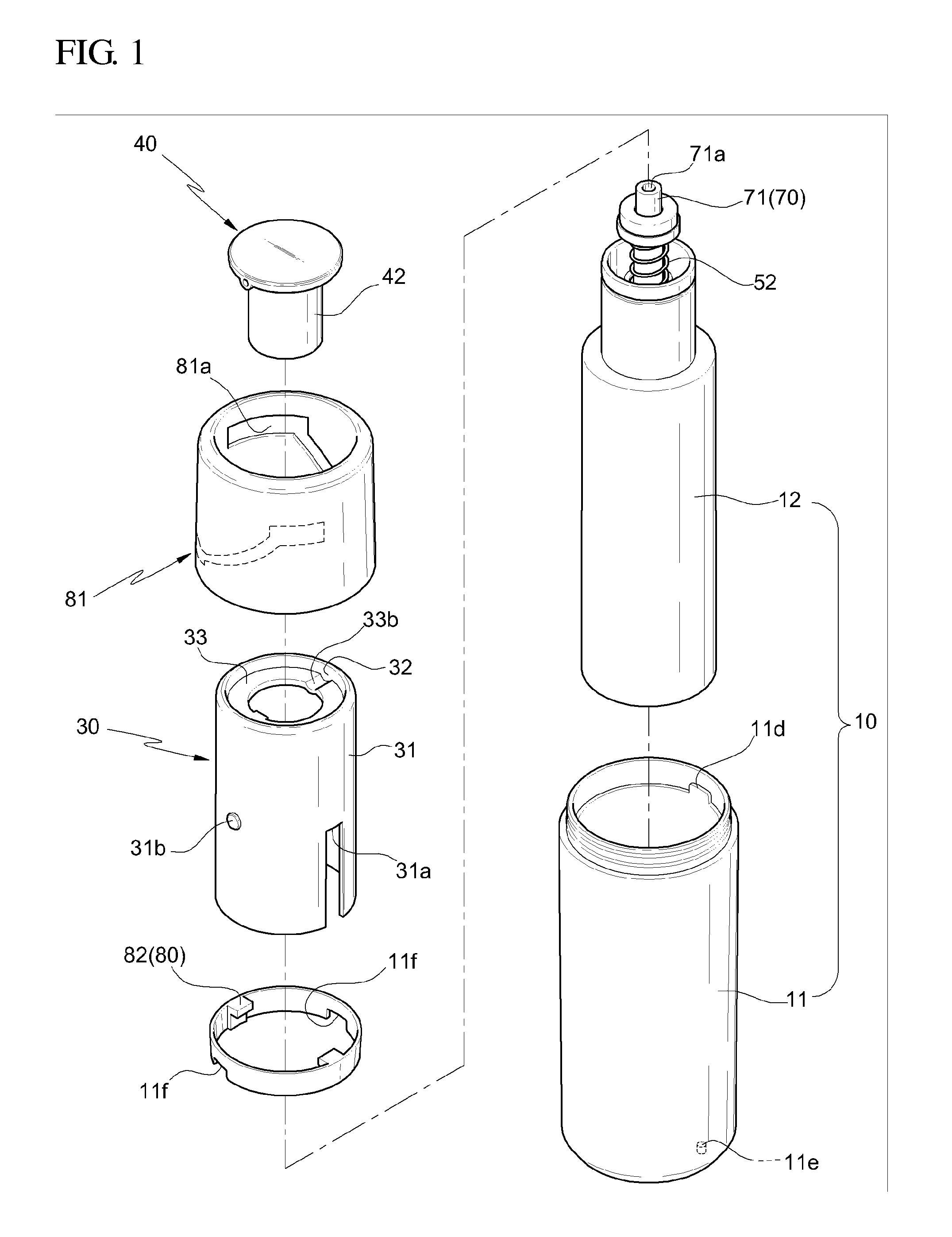
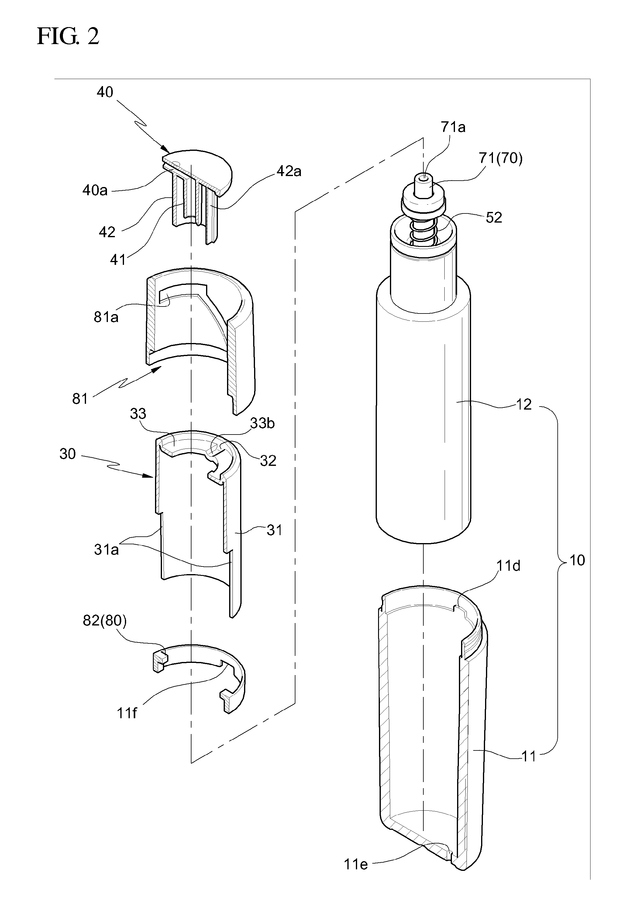
[0088]FIGS. 1 and 2 are exploded perspective views illustrating a cosmetic receptacle according to an embodiment of the present invention, FIG. 3 is a sectional view illustrating a cosmetic receptacle according to an embodiment of the present invention, and FIG. 4 is a plan view illustrating a valve body shown in FIG. 3.

[0089]As shown in these drawings, the cosmetic receptacle according to the embodiment of the present invention includes: a receptacle part 10 including an outer receptacle 11 and an inner receptacle 12 assembled with the interior of the outer receptacle 11; an inner cap 20 assembled with an upper end of the inner receptacle 12; a shoulder part 30 assembled with an upper end of the outer receptacle 11; a button 40 installed at the upper side of the inner cap 20; a pumping part 150 allowing liquid cosmetics kept into the inner receptacle 12 to be squeezed out when the us...


PUM


Abstract

A cosmetic receptacle includes: a button locking part including a locking operation pipe assembled with an outer surface of an upper end of the outer receptacle so as to rotate respective to the outer receptacle and a stopping protuberance protruding from an inner surface of the upper end of the outer receptacle, a locking operation groove being formed at the locking operation pipe, the locking operation groove including a lock keeping groove arranged at an upper area of the locking operation groove along a horizontal direction, a release keeping groove arranged at a lower area of the locking operation groove along a horizontal direction, and an elevation guide groove connecting the lock keeping groove with the release keeping groove in a linear direction, and a shoulder part including a stopper groove formed on the shoulder part along a longitudinal direction and an elevation leading protuberance formed at an outer surface of the shoulder part, the shoulder part being installed in such a manner that the stopping protuberance is inserted into the stopper groove, and that the elevation leading protuberance is inserted into the locking operation groove.

Description

BACKGROUND OF THE INVENTION[0001]1. Field of the Invention[0002]The present invention relates to a cosmetic receptacle, and more particularly to a cosmetic receptacle having a structure allowing a user to squeeze out liquid cosmetics kept in the receptacle through a pumping operation so as to use it.[0003]2. Description of the Prior Art[0004]In general, liquid cosmetics kept in a receptacle are sold, and a user squeezes a bit of the liquid cosmetics kept in the receptacle so as to use it. In order to achieve this, a cosmetic receptacle having a pumping part was invented and is generally used nowadays.[0005]FIG. 15 is an exploded perspective view illustrating a conventional cosmetic receptacle, and FIG. 16 is a sectional view illustrating a conventional cosmetic receptacle which is assembled.[0006]As shown in these drawings, the conventional cosmetic receptacle includes: a receptacle part 110 including an outer receptacle 111 and an inner receptacle 112 assembled with the interior of...

Claims


Application Information

Patent Timeline
IPC IPC(8): B67D5/00B67D5/06B67D99/00B67D7/06
CPCA45D34/04A45D2200/056B05B11/0032B05B11/0048B05B11/3074B05B11/3023B05B11/3059B05B11/3067B05B11/3069B05B11/0054B05B11/0038B05B11/028B05B11/1023B05B11/1059B05B11/1067B05B11/1069B05B11/1074A45D34/00
Inventor BAE, HAE DONG
Owner TAESUNG IND
Why Eureka
Try Eureka