Unlock instant, AI-driven research and patent intelligence for your innovation.

High light extraction efficiency light emitting diode (LED) using glass packaging

a technology of light-emitting diodes and glass packaging, which is applied in the direction of electrical apparatus, semiconductor/solid-state device manufacturing, and semiconductor devices, etc., can solve the problems of reducing efficiency or output power of leds, and achieve high light extraction, high refractive index of glass materials, and high power leds

Inactive Publication Date: 2009-05-14
RGT UNIV OF CALIFORNIA
View PDF59 Cites 83 Cited by
  • Summary
  • Abstract
  • Description
  • Claims
  • Application Information

AI Technical Summary

Benefits of technology

[0035]The present invention describes LED packages using glass materials and their fabrication. In particular, the invention is effective in high power LEDs. The present invention achieves high light extraction via high refractive indices of glass materials and high LED drive currents via high thermal conductivities of glass materials. As a result, overall LED efficiency is improved and high luminous flux is obtained.
[0036]The present invention describes a high efficient LED by minimizing the internal reflection inside of a sphere-shaped molded package, which is made from glass. Assuming that the LED is a point light source and the size of the package is large, the direction of the all of the LED light beams to perpendicular to the surface of the package as shown in FIG. 1. Thus, all of the light can be extracted from the spherical LED package.
[0037]Also, the present invention describes an (Al, Ga, In)N and light emitting diode (LED) in which the multi directions of light can be extracted from the surfaces of the chip before entering the sphere shaped optical element and subsequently extracted to air. In particular the (Al, Ga, In)N and transparent contact layers (ITO or ZnO) is combined with a sphere shaped lens in which most light entering lens lies within the critical angle and is therefore extracted. The present includes invention minimizing the internal reflection of LED light by mirrors without any intentional mirrors attached to LED chip in order to minimize the re-absorption of the LED light by the emitting layer (or the active layer) of the LED. In order to minimize the internal reflection of the LED light, transparent electrodes such as ITO or ZnO, or the surface roughening of AlInGaN by patterning or anisotropically etching, are used to extract more light from the LED. The present invention furthermore combines the high light extraction efficiency LED chip with shaped (textured) phosphor layers to increase the total luminous efficacy of the device. As a result, this combined structure extracts more light out of the LED.

Problems solved by technology

Thus, the efficiency or output power of the LEDs is decreased due to the re-absorption of LED light by the emitting layer.

Method used


Image

  • High light extraction efficiency light emitting diode (LED) using glass packaging
  • High light extraction efficiency light emitting diode (LED) using glass packaging
  • High light extraction efficiency light emitting diode (LED) using glass packaging

Examples


Embodiment Construction

[0052]In the following description of the preferred embodiment, reference is made to the accompanying drawings which form a part hereof, and in which is shown by way of illustration a specific embodiment in which the invention may be practiced. It is to be understood that other embodiments may be utilized and structural changes may be made without departing from the scope of the present invention.

[0053]Overview

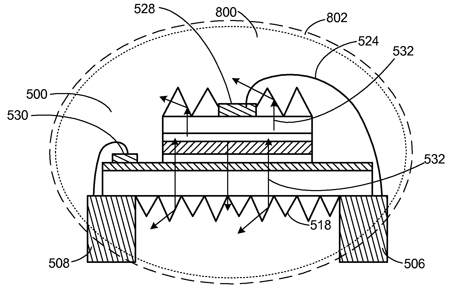
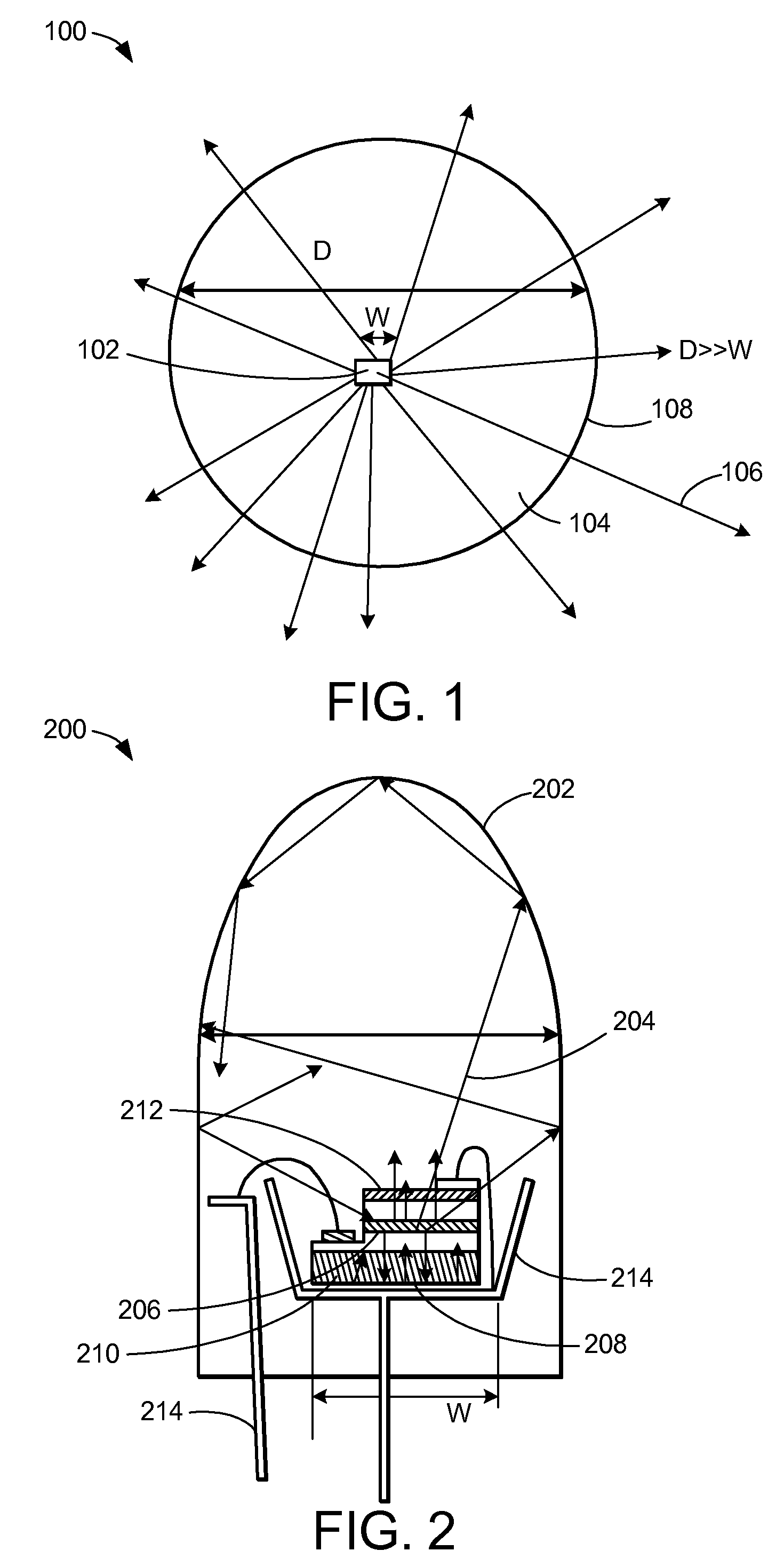
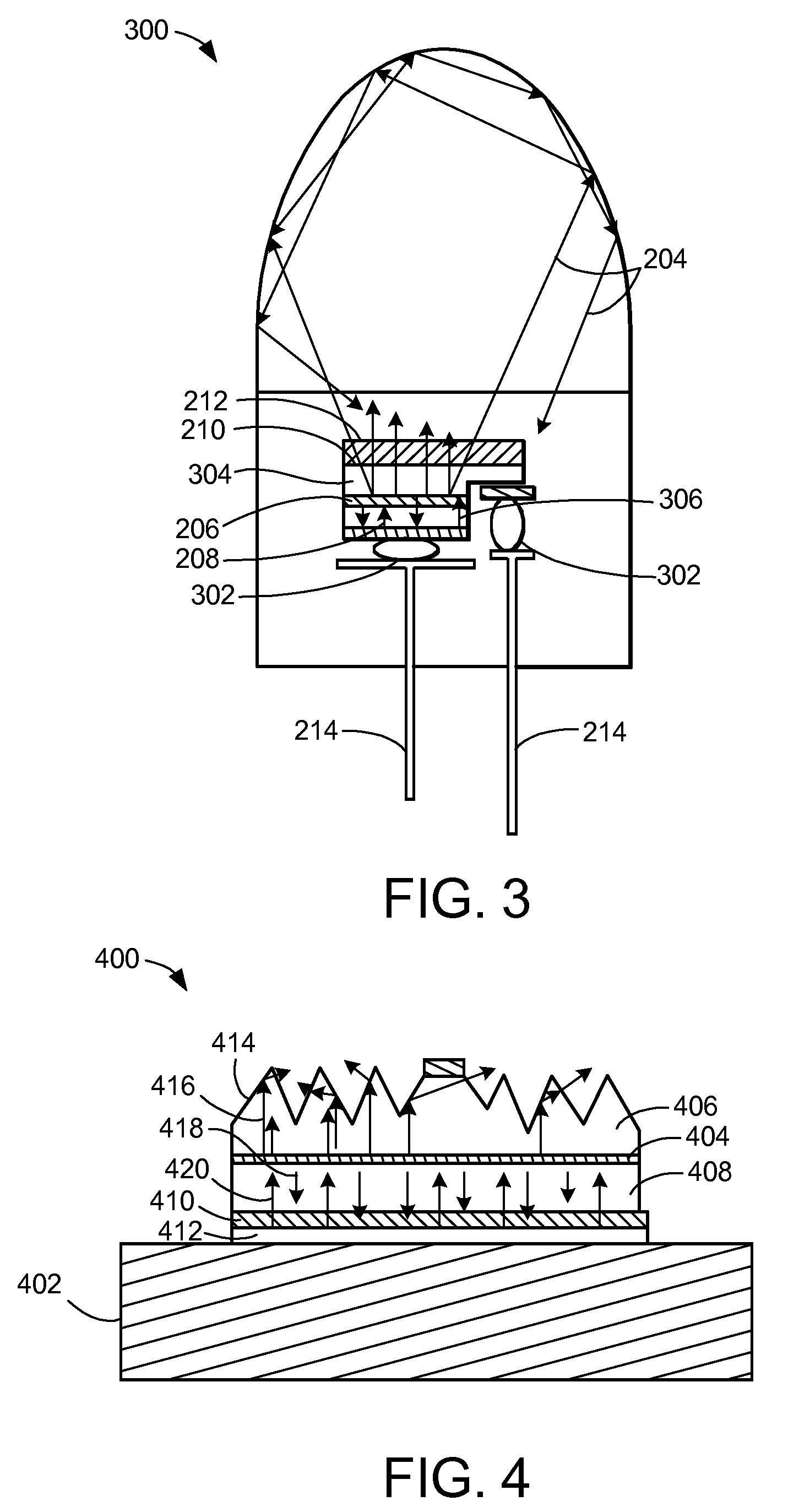
[0054]The present invention describes a high efficiency LED which minimizes the internal reflection inside of a sphere-shape package. If the LED is considered a point light source and the size of the sphere-shape package is large compared to the LED chip itself, the direction of the LED light beams is approximately perpendicular to the surface of the sphere-shape package. Then, all of the light that is emitted from the LED is extracted from the sphere-shape package into air.

[0055]The present invention also increases light extraction efficiencies and improves thermal characteri...


PUM


Abstract

An (Al, Ga, In)N and ZnO direct wafer bonded light emitting diode (LED) combined with a shaped optical element in which the directional light from the ZnO cone or any high refractive index material in contact with the LED surface entering the shaped optical element is extracted to air.

Description

CROSS-REFERENCE TO RELATED APPLICATIONS[0001]This application is a continuation-in-part of the following co-pending and commonly-assigned applications:[0002]U.S. Utility patent application Ser. No. 11 / 940,872, filed on Nov. 15, 2007, by Steven P. DenBaars, Shuji Nakamura and Hisashi Masui, entitled “HIGH LIGHT EXTRACTION EFFICIENCY SPHERE LED,” attorney's docket number 30794.204-US-U1 (2007-271-2), which application claims the benefit under 35 U.S.C Section 119(e) of U.S. Provisional Patent Application Ser. No. 60 / 866,025, filed on Nov. 15, 2006, by Steven P. DenBaars, Shuji Nakamura and Hisashi Masui, entitled “HIGH LIGHT EXTRACTION EFFICIENCY SPHERE LED,” attorney's docket number 30794.204-US-P1 (2007-271-1);[0003]which applications are incorporated by reference herein.[0004]This application is related to the following co-pending and commonly-assigned applications:[0005]U.S. Utility application Ser. No. 10 / 581,940, filed on Jun. 7, 2006, by Tetsuo Fujii, Yan Gao, Evelyn. L. Hu, an...

Claims


Application Information

Patent Timeline
IPC IPC(8): H01L33/00H01L21/02H01L33/22H01L33/44H01L33/48H01L33/50H01L33/54H01L33/56
CPCH01L33/22H01L33/44H01L33/483H01L33/507H01L33/54H01L33/56H01L2933/0091H01L2224/73265H01L2224/48091H01L2224/48247H01L2224/49107H01L2924/00014H01L2224/16245H01L2224/48257H01L2924/181H01L2924/00012
Inventor DENBAARS, STEVEN P.NAKAMURA, SHUJIMASUI, HISASHI
Owner RGT UNIV OF CALIFORNIA