Method of manufacturing ring-shaped member, backup ring and seal structure for fuel injection valve

a technology of fuel injection valve and flange, which is applied in the direction of machines/engines, mechanical equipment, metal working equipment, etc., can solve the problems of reducing the lifespan reducing the responsiveness reducing the efficiency of the fuel injection valve, so as to achieve excellent pressure resistance, ensure the thickness and height of the flange portion to be formed, and efficiently manufactured

Inactive Publication Date: 2009-05-14
BOSCH CORP +1
View PDF4 Cites 13 Cited by
  • Summary
  • Abstract
  • Description
  • Claims
  • Application Information

AI Technical Summary

Benefits of technology

[0020]According to the method of manufacturing ring-shaped member of the present invention, by performing burring as a finishing process after bending the edge portion of the prepared hole a predetermined extent beforehand, both the thickness and height of the flange portion to be formed can be ensured even when the ring-shaped member is manufactured using a relatively thick base material. Consequently, a ring-shaped member that has excellent resistance to pressure and resistance to shock can be efficiently manufactured. It will be noted that a ring-shaped member with a predetermined shape can be more economically and efficiently manufactured in comparison also to when the ring-shaped member is manufactured by forging.
[0021]Further, according to the backup ring of the present invention and the seal structure for a fuel injection valve using the backup ring, the thickness of the flat portion is relatively thick, both the thickness and the height of the flange portion are ensured, its strength is improved, and extrusion of the seal member and stopping of the internal combustion engine accompanying that can be effectively prevented even when the fuel pressure is relatively high.

Problems solved by technology

Moreover, when part accuracy, eccentricity, or requirements during assembly are compounded, there is also the potential for the seal member 322 to be pressed out in the direction of the gap 328 so that the seal member becomes unable to retain its seal function.
Because of such a drop in seal function, there is the potential for this to lead not only to a shift in the injection timing in the back pressure control component (not shown) and a drop in responsiveness but also a drop in the lifespan of the fuel injection valve (not shown).

Method used


Image

  • Method of manufacturing ring-shaped member, backup ring and seal structure for fuel injection valve
  • Method of manufacturing ring-shaped member, backup ring and seal structure for fuel injection valve
  • Method of manufacturing ring-shaped member, backup ring and seal structure for fuel injection valve

Examples


first embodiment

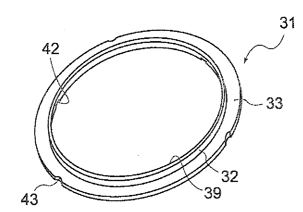
[0032]A first embodiment of the present invention is a method of manufacturing a ring-shaped member that is manufactured by subjecting a rigid flat-shaped base material to burring, with the ring-shaped member comprising an open portion in its center, a flat portion that is disposed around the open portion, and a flange portion that is disposed between the open portion and the flat portion, overlaps the flat portion, and is raised in a perpendicular direction with respect to the flat portion.

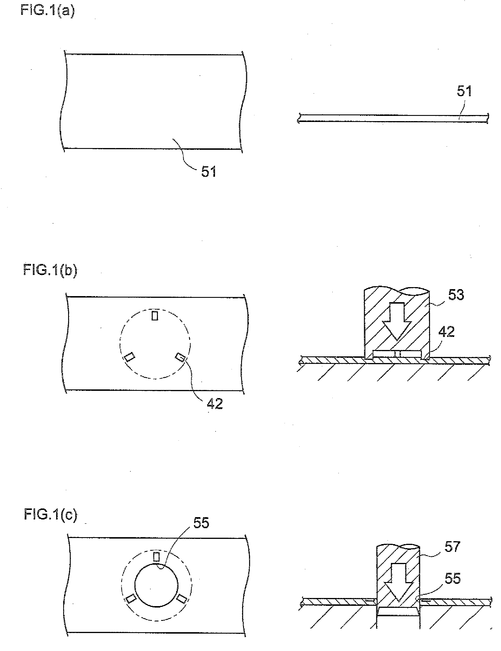
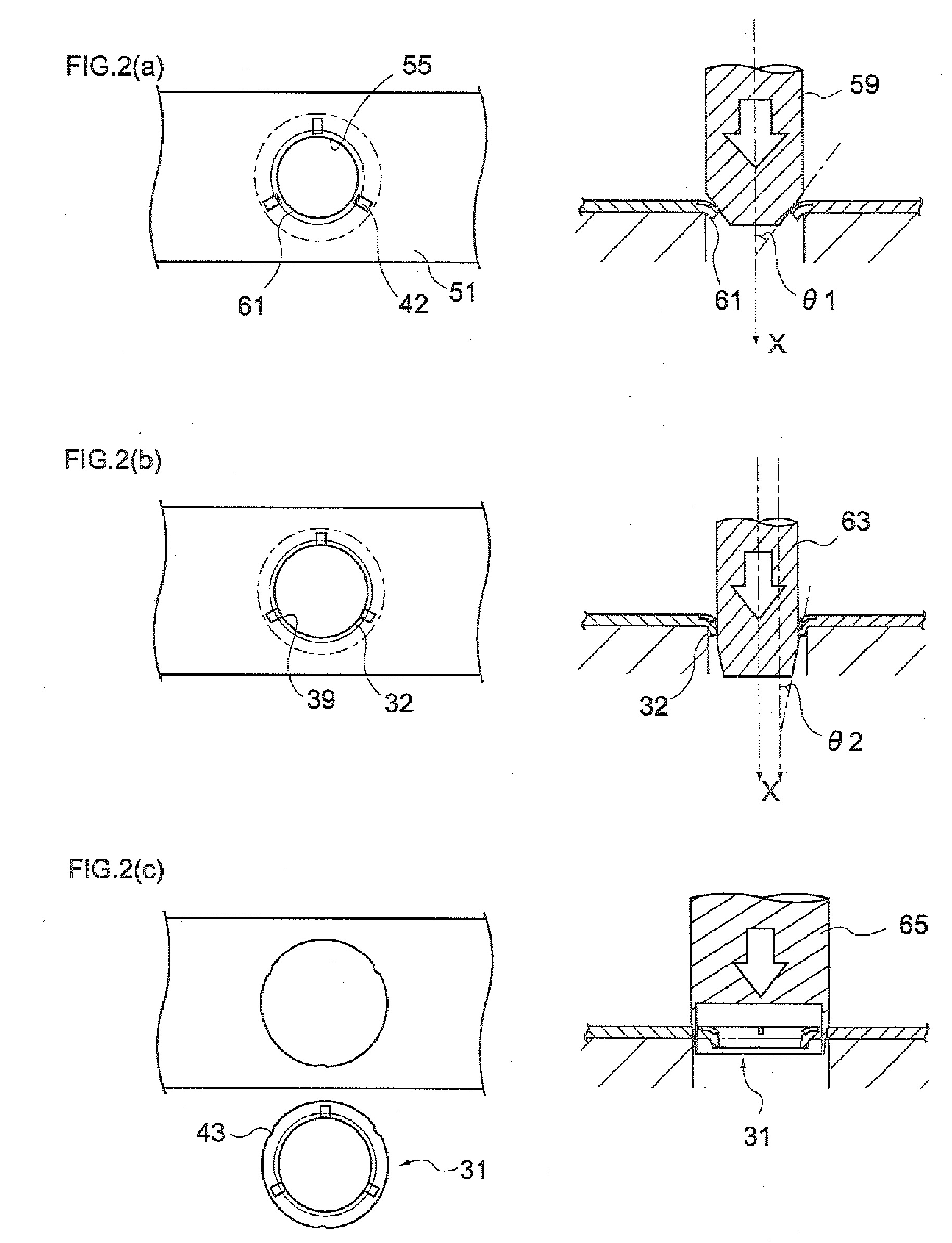
[0033]The method of manufacturing a ring-shaped member includes: a step of forming a prepared hole with respect to the base material; a step of pressing an edge portion of the prepared hole to thereby bend the edge portion using a first punch member that has a diameter that is larger than the diameter of the prepared hole and is tapered towards its distal end portion; and a step of forming the flange portion by press-inserting, with respect to the prepared hole whose edge portion has been bent, a...

second embodiment

[0065]A second embodiment of the present invention is a seal structure for a fuel injection valve having an annular seal member that is disposed in a pressure introduction chamber for sealing so that high-pressure fuel inside the pressure introduction chamber does not escape to a low pressure side from a gap formed between an injector housing and a valve body into which a valve piston has been slidably inserted.

[0066]The seal structure for a fuel injection valve includes, between the gap and the seal member, a backup ring for reinforcing the seal member, the backup ring includes an open portion in its center, a flat portion that is disposed around the open portion, and a flange portion that is disposed between the open portion and the flat portion, overlaps the flat portion, and is raised in a perpendicular direction with respect to the flat portion, and the backup ring is manufactured by a method including forming a prepared hole with respect to a rigid base material, thereafter pr...


PUM

PropertyMeasurementUnit
thicknessaaaaaaaaaa
thicknessaaaaaaaaaa
heightaaaaaaaaaa

Abstract

To provide: a method of manufacturing a ring-shaped member that can efficiently manufacture a stronger backup ring that reinforces a seal member disposed in a pressure introduction chamber of a fuel injection valve; the backup ring; and a seal structure for a fuel injection valve disposed with the backup ring.
A method of manufacturing a ring-shaped member that is manufactured by subjecting a rigid flat-shaped base material to burring includes: a step of forming a prepared hole with respect to the base material; a step of pressing an edge portion of the prepared hole to thereby bend the edge portion using a first punch member that has a diameter that is larger than the diameter of the prepared hole and is tapered towards its distal end portion; and a step of forming a flange portion by press-inserting, with respect to the prepared hole whose edge portion has been bent, a second punch member that has a diameter that is smaller than the diameter of the first punch member and is tapered towards its distal end portion.

Description

TECHNICAL FIELD[0001]The present invention relates to a method of manufacturing a ring-shaped member, a backup ring, and a seal structure for a fuel injection valve. In particular, the present invention relates to a method of manufacturing a ring-shaped member suited for a backup ring used in a fuel injection valve that injects, at a predetermined timing, high-pressure fuel supplied from a pressure accumulator (common rail) or the like, a backup ring manufactured by the method of manufacturing a ring-shaped member, and a seal structure for a fuel injection valve using the backup ring.BACKGROUND ART[0002]Conventionally, in a fuel injection system of an internal combustion engine, a fuel injection valve for supplying fuel to cylinders of the internal combustion engine is given a configuration that mainly includes an injector housing, a nozzle body, a nozzle needle, a valve piston, a valve body, a back pressure control component, and a connecting rod. Additionally, when the fuel inject...

Claims


Application Information

Patent Timeline
Patent Type & Authority Applications(United States)
IPC IPC(8): F16J15/34B26F1/40F02M61/16
CPCB21D53/20F02M47/027F02M55/005F02M2547/003F02M2200/8053F02M2200/8061F02M2200/8069F02M61/168Y10T83/0481
Inventor UOZUMI, YASUFUMIMOCHIZUKI, EIJI
Owner BOSCH CORP
Why Eureka
Try Eureka