
Direct current motor

Inactive Publication Date: 2009-05-14
ASMO CO LTD
View PDF6 Cites 7 Cited by
  • Summary
  • Abstract
  • Description
  • Claims
  • Application Information

AI Technical Summary

Benefits of technology

[0005]Accordingly, it is an objective of the present invention to provide an easy-to-manufacture and highly reliable direct current motor that reduces vibration and noise by ensuring uniform distribution of excitation force in the stator.

Problems solved by technology

This causes great strain in the yoke, thus producing great vibration and high noise disadvantageously.
In this case, the vibration and noise aggravates.
Further, since the interval between each adjacent pair of the segments decreases, the fusing must be carried out in a limited space.
This may trigger erroneous short circuits of the coil, thus lowering reliability.

Method used


Image

  • Direct current motor
  • Direct current motor
  • Direct current motor

Examples


Embodiment Construction

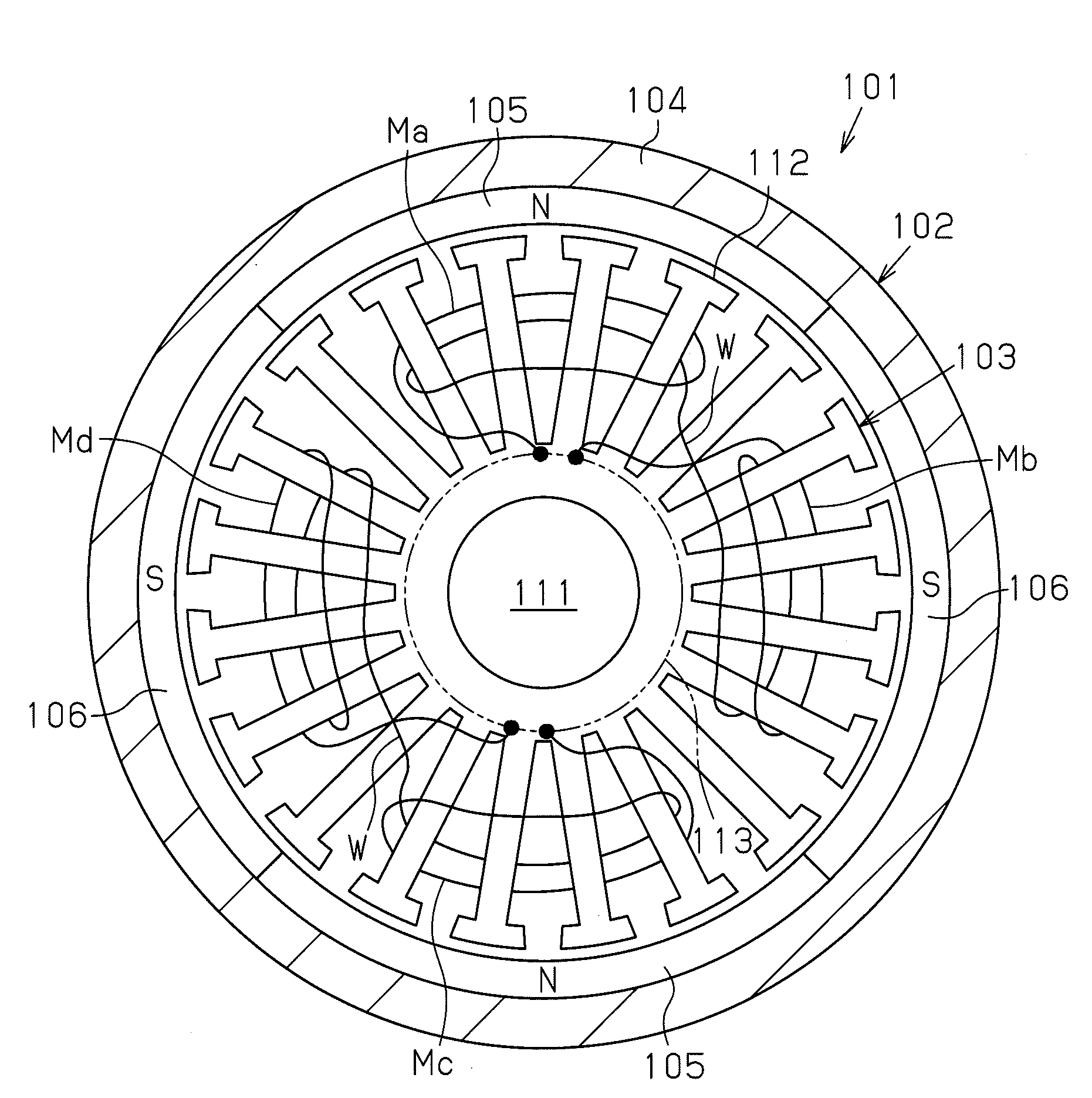
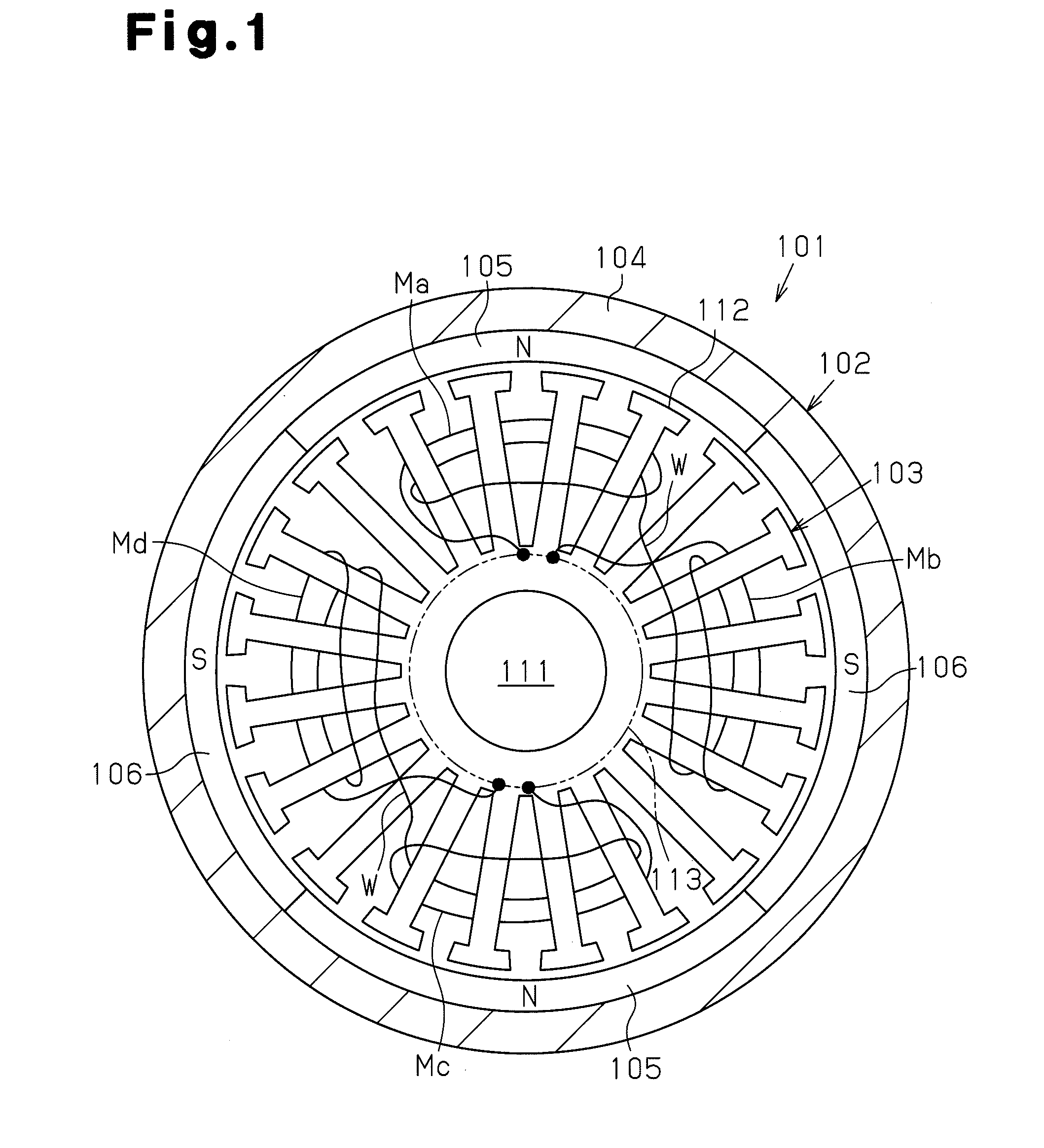
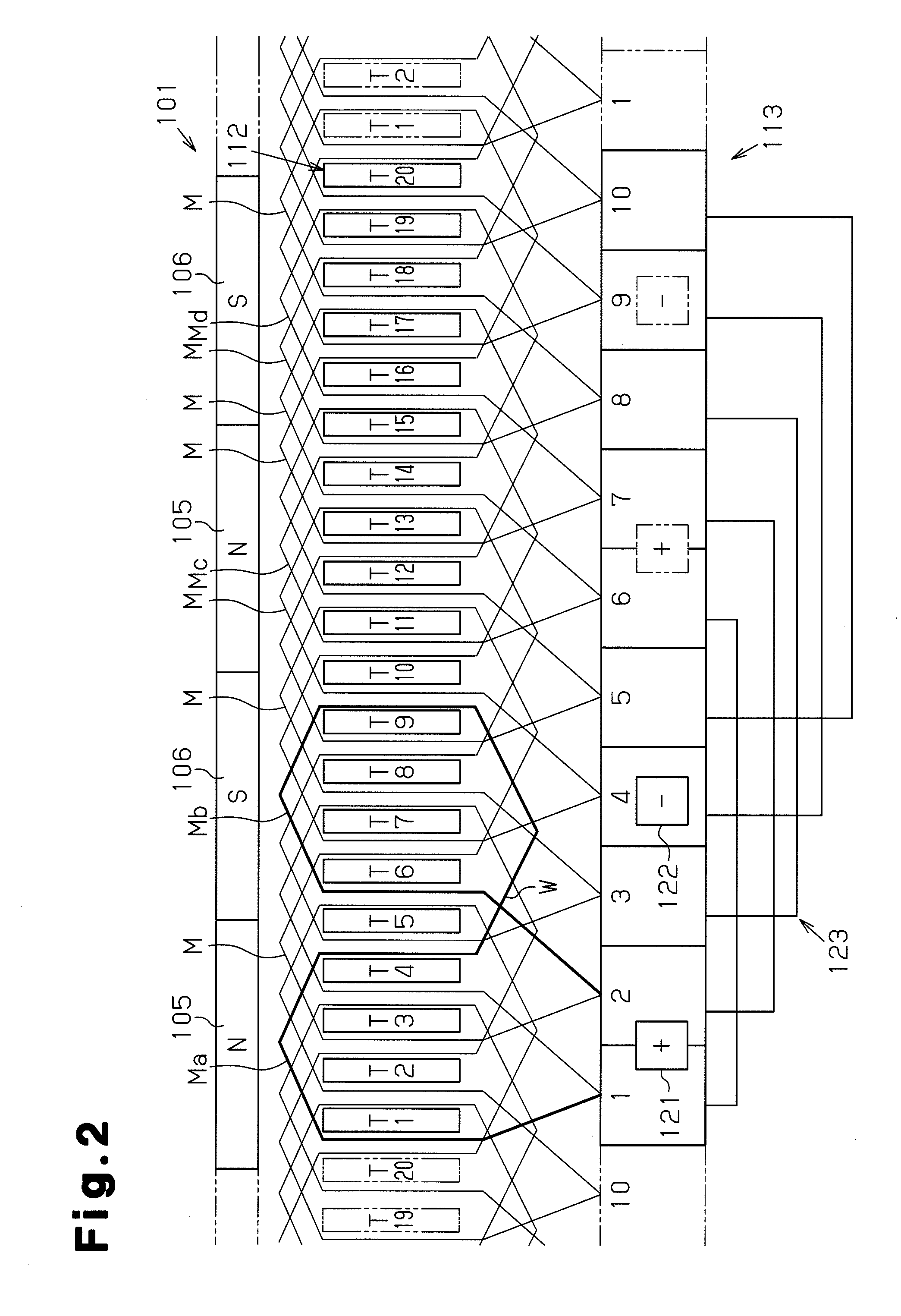
[0021]One embodiment of the present invention will now be described with reference to FIGS. 1 and 2.

[0022]As illustrated in FIG. 1, a direct current motor 101 of the present embodiment has a stator 102 and an armature (a rotor) 103. The stator 102 has a yoke housing 104, which is a substantially cylindrical yoke, and magnets 105, 106, the number of which is represented by 2P (P is an integer not less than two). The magnets 105, 106 are fixed to the inner circumferential surface of the yoke housing 104 and arranged at equal angular intervals. In the present embodiment, P is 2, and a total of four magnets including two N pole magnets 105 and two S pole magnets 106 are arranged at intervals of 90° in such a manner that the N pole magnets 105 and the S pole magnets 106 are arranged alternately in the circumferential direction. In other words, a total of four magnetic poles are arranged at 90° in the circumferential direction in such a manner that the different magnetic poles are provide...


PUM


Abstract

A direct current motor is disclosed. The motor includes a stator, a commutator, an armature core, and brushes. The stator has a yoke and magnetic poles. The magnetic poles are arranged at a predetermined pitch along a circumferential direction of the yoke. The number of the magnetic poles is represented by the expression: 2×P (P is an integer not less than 2). The commutator has segments that are arranged in a circumferential direction of the commutator. The number of the segments is represented by the expression: P×N (N is an odd number not less than 3). The armature core is rotatable integrally with the commutator and includes teeth provided by the number represented by the expression: 2×P×N. A coil is wound around the teeth by distributed winding. Each one of the brushes is pressed against and contacts the segments. Two of the segments that are electrically short-circuited by one of the brushes are connected to each other by at least two coils that are arranged at an interval corresponding to an integral multiple of the pitch (360° / (2×P)) of the magnetic poles.

Description

BACKGROUND OF THE INVENTION[0001]The present invention relates to a direct current motor having a stator with four or more magnetic poles.[0002]Japanese Laid-Open Patent Publication No. 2006-121833 discloses a direct current motor having a stator including four magnetic poles, a commutator having ten segments, an armature core that is rotatable integrally with the commutator, and a pair of brushes (an anode brush and a cathode brush) that slidably contact the segments. The magnetic poles are fixed to a yoke to be aligned in a circumferential direction of the yoke. The segments are arranged in a circumferential direction of the commutator to be opposed to the magnetic poles. The armature core has ten teeth, and a coil is wound around the teeth by distributed winding.[0003]In the direct current motor, commutation is executed at different timings for the anode brush and the cathode brush. The positions of the teeth (or, the coils) relative to the magnetic poles at one of these timings ...

Claims


Application Information

Patent Timeline
IPC IPC(8): H02K3/28
CPCH02K23/26
Inventor AOYAMA, TOMOHIROYAMAMOTO, TOSHIOMORIYA, KAZUMITSU
Owner ASMO CO LTD
Learn More