Electric power steering device

a technology of electric power steering and electric motor, which is applied in the direction of steering initiation, instruments, vessel construction, etc., can solve the problems of conflicting needs for using bulky electric motors, large size of insufficient output torque of electric motors in direct-drive electric power steering devices. , to achieve the effect of reducing vibration or noise, reducing the size of electric power steering devices, and reducing weigh

Inactive Publication Date: 2011-11-29
JTEKT CORP
View PDF24 Cites 0 Cited by
  • Summary
  • Abstract
  • Description
  • Claims
  • Application Information

AI Technical Summary

Benefits of technology

[0009]The invention reduces the size of an electric power steering device. The invention also provides an electric power steering device that reduces vibrations or noise and / or has a reduced weight.
[0011]According to the first aspect of the invention, the rotational position of the rotor may be detected using the output of the input shaft rotational position sensor and the output of the steering torque sensor. That is, there is no need to dispose a rotor rotational position sensor for detecting the rotational position of the rotor inside the electric motor, thereby reducing the size of the electric motor in the axial direction. As a result, the vehicular steering device may be reduced in size. The input shaft rotational position sensor may be disposed facing the input shaft in a radial direction thereof. In this case, by disposing the input shaft rotational position sensor in an ample space around the input shaft, the vehicular steering device may further be reduced in size with the efficient use of the space around the input shaft.
[0013]According to the second aspect of the invention, the tubular portion is relatively thin. Therefore, although the end member is relatively thick, the motor housing may be reduced in weight or size as a whole. On the other hand, the end member is relatively thick. Therefore, the strength of the end member is sufficiently ensured. Accordingly, the motor housing can stably support the bearing and the steering shaft. As a result, wobbling of the steering shaft or vibrations or noise resulting from the wobbling is prevented. That is, in the second aspect of the invention, the occurrence of vibrations or noise can be prevented, and the motor housing can be reduced in weight. The tubular portion is thin, but is reinforced by the stator fixed to an inner periphery thereof. Therefore, the electric motor is ensured of a sufficient strength as a whole.
[0015]The tubular portion may be formed of a material containing iron, and the end member may be formed of a material containing aluminum. In this case, the tubular portion is formed of the material containing iron, which exhibits a relatively high strength. Therefore, the tubular portion is ensured of a sufficient strength despite the thinness thereof. The material containing aluminum is relatively light. Therefore, weight of the end member may be reduced while maintaining a sufficient strength.
[0017]In this case, by fixing the intermediate member, the end member, and the flange using the common fixing screw, the man-hours required to assemble the electric power steering device may be reduced. By fixing the above-described three components integrally, the end member is reinforced by the intermediate member and the flange. Therefore, the bearing and the steering shaft are more stably held by the end member. Thus, the occurrence of vibrations or noise is more reliably prevented.
[0018]The end member may have a tubular protrusion fitted to the inner periphery of the tubular portion. In this case, by fitting the tubular protrusion of the end member to the inner periphery of the tubular portion, the end member may be accurately positioned with respect to the tubular portion of the motor housing.

Problems solved by technology

However, the output torque of the electric motor in direct-drive type electric power-steering devices is not amplified by the reduction gear mechanism, which necessitates the use of a high-output electric motor in direct-drive type electric power-steering devices.
Accordingly, the motor used in direct drive type electric power steering devices is often bulky.
The need to use a bulky electric motor conflicts with preference for more compact electric power steering devices.
However, by forming the motor housing through pressing, there is a maximum limit to the thickness of the plate that can be produced via pressing.
Therefore, it may be impossible to ensure sufficient strength of the bearing holding portion.
In this case, the motor housing may become unable to stably support the bearing and the steering shaft due to the flexure of the bearing holding portion or the like.
As a result, the wobble of the steering shaft and vibrations or noise resulting from the wobble may occur.

Method used


Image

  • Electric power steering device
  • Electric power steering device
  • Electric power steering device

Examples


first embodiment

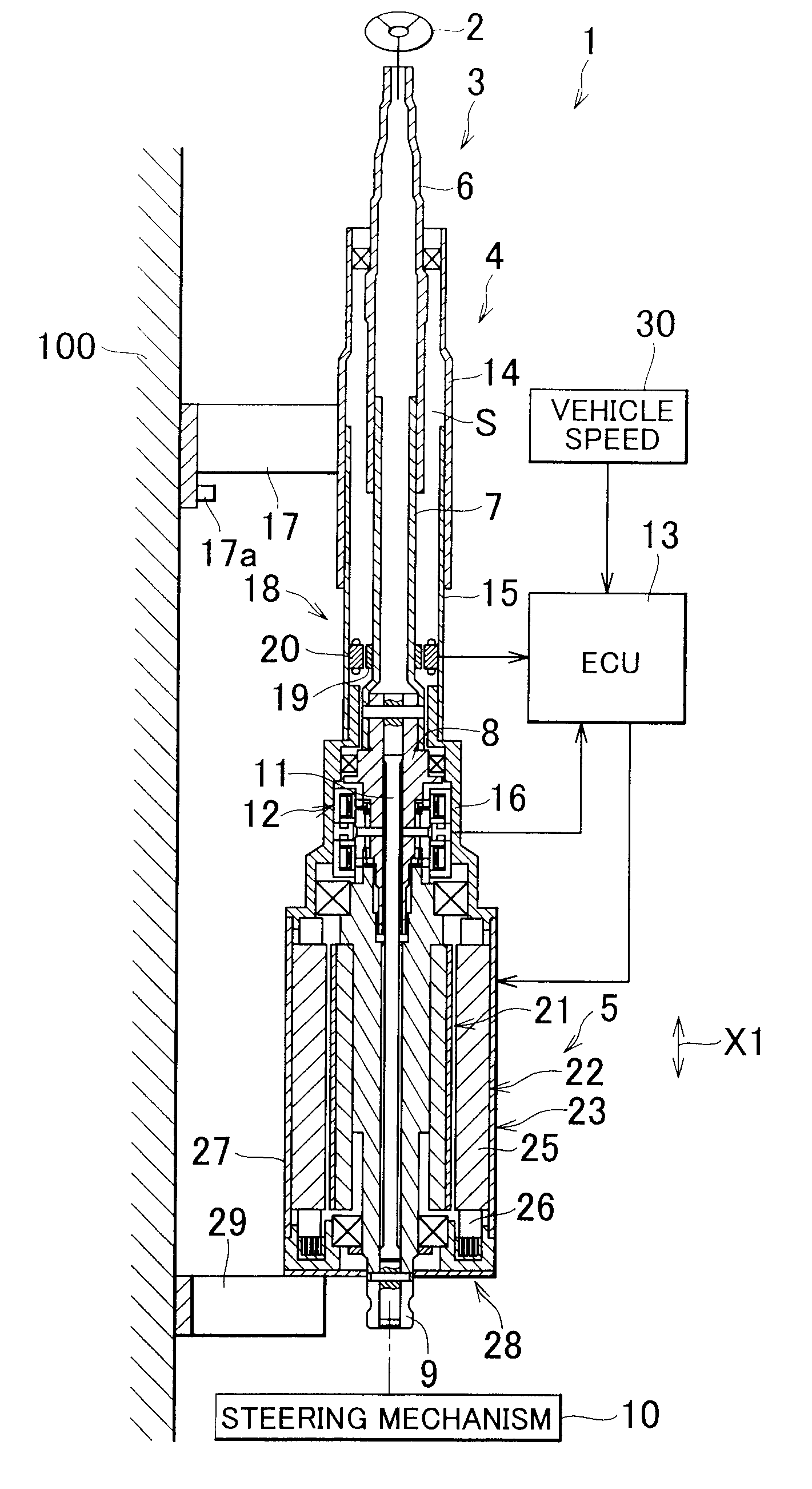
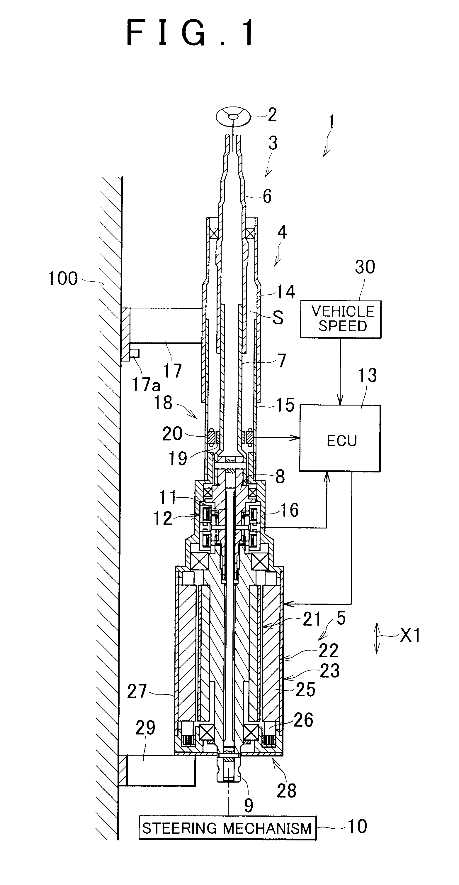
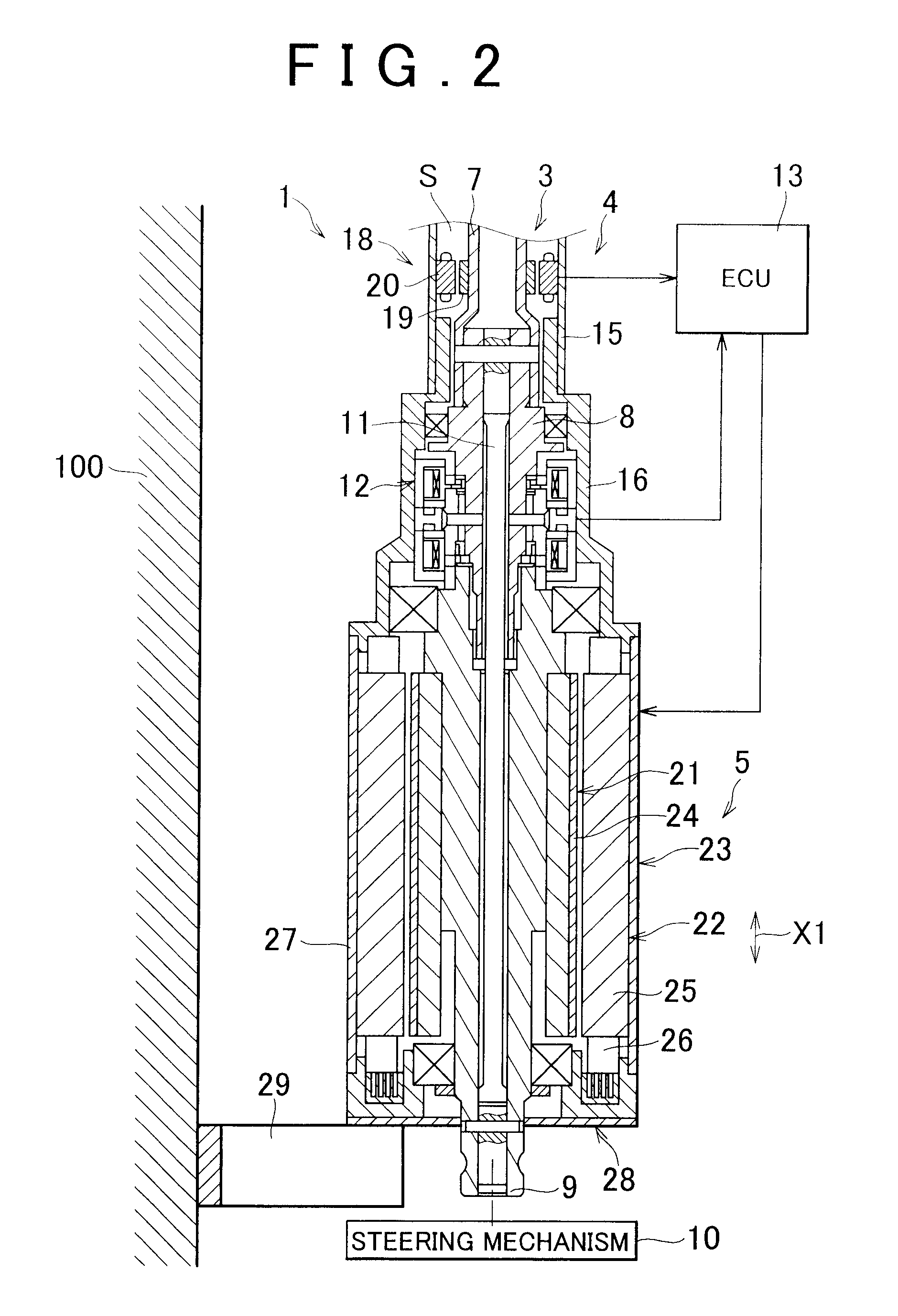
[0026]the invention will be described hereinafter with reference to FIGS. 1 to 3. FIG. 1 is a cross-sectional view showing the schematic construction of an electric power steering device 1 according to one embodiment of the invention. FIG. 2 is a cross-sectional view of part of the electric power steering device I on an enlarged scale. Referring to FIG. 1, the electric power steering device 1 is includes a steering shaft 3 to which a steering member 2 such as a steering wheel is attached; a tubular steering column 4 that rotatably supports the steering shaft 3; and an electric motor 5 that provides steering assist that is coaxially coupled to the steering shaft 3.

[0027]The steering shaft 3 is composed of a plurality of rectilinearly extending shafts. That is, the steering shaft 3 is composed of, for example, an upper shaft 6, a lower shaft 7, an input shaft 8, and an output shaft 9. The respective shafts 6 to 9 are rectilinearly extending tubular shafts disposed on the same axis. Th...

second embodiment

[0067]In the invention, sufficient thickness of the annular plate portion 74 and the inner tube 75 are ensured and hence a sufficient strength. Accordingly, the end member 62 can stably hold the bearing 84 and the output shaft 9, and can rotatably support the output shaft 9 stably.

[0068]Furthermore, in the second embodiment, the end member 62 as part of the motor housing 23 is thicker than the tubular portion 67. Therefore, an end member 62 of sufficient strength is ensured that can stably support the output shaft 9 via the bearing 84. Accordingly, the wobbling of the output shaft 9 or the occurrence of vibrations or noise resulting from the wobbling of the output shaft 9 is prevented. Part of the end member 62 (the region 74a of the annular plate portion 74) is reinforced by being sandwiched by the intermediate member 36 and the flange 68 in the axial direction X1. Therefore, the bearing 84 and the output shaft 9 are more stably held by the end member 62. Thus, the wobbling of the ...


PUM


Abstract

A steering shaft is composed of an upper shaft, a lower shaft, an input shaft, and an output shaft. The upper shaft, the lower shaft, and the input shaft can rotate together, and the input shaft and the output shaft are relatively rotatably coupled to each other via a torsion bar. The rotational position of a rotor coupled to the output shaft is calculated based on the detected rotational position of the lower shaft and a steering torque detected based on the amount of relative rotational displacement of the input shaft and the output shaft. Thus, it is not necessary to include a rotor rotational position detecting unit for detecting the rotational position of the rotor within the electric motor, which reduces the size of the electric motor.

Description

INCORPORATION BY REFERENCE[0001]The disclosures of Japanese Patent Applications No. 2007-123695 filed on May 8, 2007 and No. 2007-160219 filed on Jun. 18, 2007 including the specifications, drawings and abstracts are incorporated herein by reference in their entirety.BACKGROUND OF THE INVENTION[0002]1. Field of the Invention[0003]The invention relates to an electric power steering device used in a vehicle such as an automobile or the like.[0004]2. Description of the Related Art[0005]An electric power steering device of so-called direct drive type, with an electric motor whose output torque is directly transmitted to a steering shaft without the intervention of a reduction gear mechanism, is described in, for example, Japanese Patent Application Publication No. 2005-145436 (JP-A-2005-145436).[0006]An electric power steering device is equipped with an electric motor to provide assistance in steering. Generally, there is limited space within the vehicle to place the electric power-stee...

Claims


Application Information

Patent Timeline
Patent Type & Authority Patents(United States)
IPC IPC(8): B62D5/14B62D6/10B62D5/04
CPCB62D5/0403B62D5/0415B62D15/0215
Inventor YOSHIOKA, KAZUYAYOSHII, YASUYUKIHIGASHI, KENJIJIMBO, SHIMONNAKA, MASAMINAKANO, SHIRO
Owner JTEKT CORP
Why Eureka
Try Eureka