Electric power source device equipped with transformer

a technology of electric power source device and transformer, which is applied in the direction of electric variable regulation, process and machine control, instruments, etc., can solve the problems of difficult to reduce the overall size of the electric power source device, difficulty in downsizing the circuit substrate, and difficulty in correctly arranging the circuit substrate in a miniaturized size, so as to reduce the overall area of the circuit substrate. , the effect of increasing the overall area of the circuit substra

Active Publication Date: 2015-01-29
DENSO CORP
View PDF1 Cites 9 Cited by
  • Summary
  • Abstract
  • Description
  • Claims
  • Application Information

AI Technical Summary

Benefits of technology

[0007]It is therefore desired to provide an electric power source device having an improved structure capable of easily reducing an overall size of the electric power source device.
[0009]In the structure of the electric power source device previously described, the first circuit substrate and the second circuit substrate are arranged so that the first circuit substrate is arranged parallel to the base plate, and the second circuit substrate is arranged parallel to the direction of a normal line of the first circuit substrate. This improved structure makes it possible to suppress the overall area of the circuit substrates from expanding in a specified direction.
[0010]That is, the overall area of the circuit substrates becomes increased in the direction of a normal line thereof when a plurality of the circuit substrates is arranged parallel to the longitudinal direction, i.e. the major direction thereof. The overall area of the circuit substrate becomes increased when necessary circuit components are arranged on a single circuit substrate.
[0011]On the other hand, the electric power source device according to the present invention has the improved structure as previously described. In particular, the second circuit substrate is arranged parallel to the direction of a normal line of the first circuit substrate. In other words, the normal line of the first circuit substrate is arranged in a direction which is perpendicular to the normal line of the second circuit substrate. This improved structure of the electric power source device makes it possible to prevent the overall area of the plurality of the circuit substrates from being expanded in a specified direction. As a result, this improved structure makes it possible to suppress the overall size of the electric power source device from increasing in a specified direction, and provide the electric power source device having a miniaturized structure.

Problems solved by technology

However, it is difficult to perform downsizing of the circuit substrate when compared with the downsizing of other components because the circuit substrate has a wide area which expands in 2 dimensions.
The recent trend of downsizing of the electric power source device causes a difficulty of correctly arranging the circuit substrate in a miniaturized size.
In other words, it becomes difficult to reduce an overall size of the electric power source device because of having the circuit substrate.

Method used


Image

  • Electric power source device equipped with transformer
  • Electric power source device equipped with transformer
  • Electric power source device equipped with transformer

Examples


first exemplary embodiment

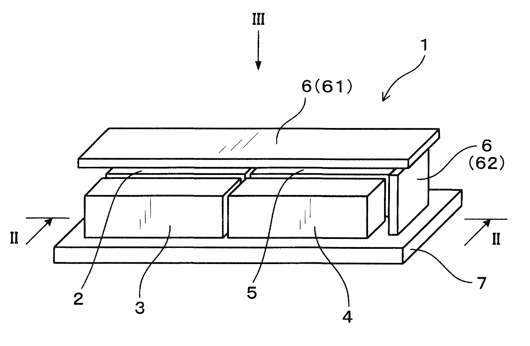
[0033]A description will be given of the electric power source device 1 according to a first exemplary embodiment with reference to FIG. 1 to FIG. 4.

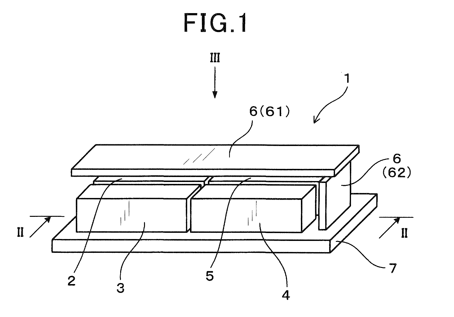
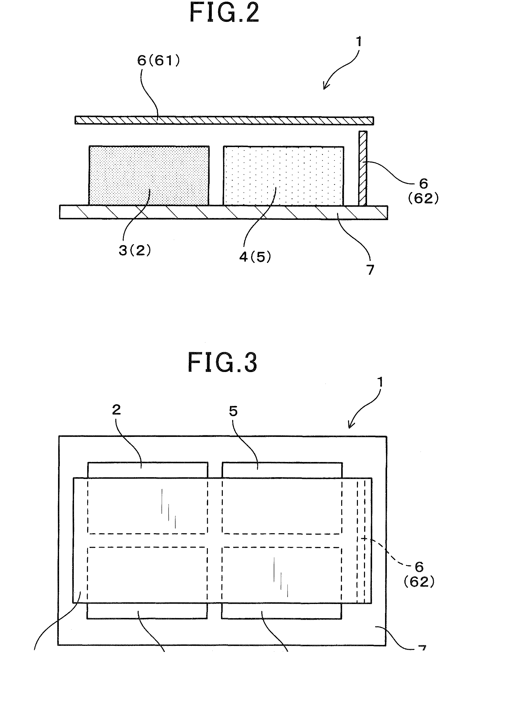
[0034]FIG. 1 is a perspective view showing an overall structure of the electric power source device 1 according to the first exemplary embodiment. FIG. 2 is a view showing a cross section of the electric power source device 1 along the line II-II shown in FIG. 1. FIG. 3 is a view showing a cross section of the electric power source device 1 along the line shown in FIG. 1.

[0035]As shown in FIG. 1, FIG. 2 and FIG. 3, the electric power source device 1 according to the first exemplary embodiment has a transformer 2, a primary side semiconductor component 3, a secondary side semiconductor component 4 and a choke coil 5. The transformer 2 is comprised of a primary coil and a secondary coil. The primary side semiconductor component 3 forms a primary side circuit connected to the primary coil of the transformer 2. The secondary side semiconduc...

second exemplary embodiment

[0057]A description will be given of the electric power source device 1 according to the second exemplary embodiment with reference to FIG. 5.

[0058]FIG. 5 is a perspective view showing an overall structure of the electric power source device 1 according to the second exemplary embodiment. The concept of the electric power source device 1 according to the second exemplary embodiment has a structure in which a conductive plate 11 is arranged between at least one of the transformer 2 and the choke coil 5 and at least some components in the circuit substrate 6.

[0059]As shown in FIG. 5, the conductive plate 11 is arranged between the first circuit substrate 61 and the transformer 2 and the choke coil 5. Further, the conductive plate 11 is also arranged between the first circuit substrate 11 and the primary side semiconductor component 3 and the secondary side semiconductor component 4. For example, the conductive plate 11 is made of a copper plate. However, it is possible to form the con...

third exemplary embodiment

[0064]A description will be given of the electric power source device 1 according to the third exemplary embodiment with reference to FIG. 6.

[0065]FIG. 6 is a perspective view showing an overall structure of the electric power source device 1 according to the third exemplary embodiment.

[0066]The electric power source device 1 according to the third exemplary embodiment has a structure in which at least two components of the transformer 2, the primary side semiconductor component 3, the secondary side semiconductor component 4 and the choke coil 5 are stacked in the direction of a normal line of the base plate 7 to form a stacked section 12.

[0067]In the structure of the electric power source device 1 according to the third exemplary embodiment, the primary side semiconductor component 3 and the transformer 2 are stacked together to form a first stacked section 12a and the secondary side semiconductor component 4 and the choke coil 5 are stacked together to form a second stacked secti...


PUM


Abstract

An electric power source device has a transformer, primary side semiconductor components, secondary side semiconductor components, a choke coil, a base plate and first circuit substrate and one or more second circuit substrates. The transformer has a primary side coil and a secondary side coil. The primary side semiconductor components form a primary side circuit connected to the primary side coil. The secondary side semiconductor components form a secondary side circuit connected to the secondary side coil. The choke coil has a smoothing circuit for smoothing an output voltage. The transformer, the primary side semiconductor components, the secondary side semiconductor components and the choke coil are formed on the base plate. The first circuit substrate is arranged parallel to the base plate. The second circuit substrate is arranged parallel to a normal line of the first circuit substrate.

Description

CROSS-REFERENCE TO RELATED APPLICATION[0001]This application is related to and claims priority from Japanese Patent Application No. 2013-153668 filed on Jul. 24, 2013, the contents of which are hereby incorporated by reference.BACKGROUND OF THE INVENTION[0002]1. Field of the Invention[0003]The present invention relates to electric power source devices equipped with a transformer.[0004]2. Description of the Related Art[0005]An electric power source device such as a direct current to direct current (DC-DC) converter has a transformer, a choke coil, various types of electronic components etc. Further, the electric power source device is equipped with a circuit substrate which forms a control circuit and some of a main circuit. For example, a patent document 1, Japanese patent laid open publication No. 2013-34270, discloses an electric power source device having a structure in which a circuit substrate having a large area is arranged in the inside of a housing.[0006]A recent technique p...

Claims


Application Information

Patent Timeline
Patent Type & Authority Applications(United States)
IPC IPC(8): H02M3/335H05K7/02
CPCH05K7/02H02M3/335H01F27/06H02M3/003H05K7/14322H05K7/1432
Inventor KURAUCHI, SHUJIMISAWA, KATSUTOYOTAKEMOTO, YUUKIHANDA, YUUICHIYAMASAKI, SHOTARO
Owner DENSO CORP
Why Eureka
Try Eureka