Electric parking brake for vehicles having operating load measuring device

a technology of parking brake and measuring device, which is applied in the direction of brake cylinder, anti-theft device, braking system, etc., can solve the problems of inconvenient use, complex assembly process, and possibility of safety hazards, so as to reduce the number of parts and ensure the reliability of the measured value

Inactive Publication Date: 2007-12-27
HYUNDAI MOBIS CO LTD
View PDF7 Cites 9 Cited by
  • Summary
  • Abstract
  • Description
  • Claims
  • Application Information

AI Technical Summary

Benefits of technology

[0009]Embodiments of the present invention provide an electric parking brake having an operating load measuring device which measures an operating load using a current value that varies depending on the intensity of the operating load, thus preventing a problem of the conventional art, in which a loss stroke of a spring occurs, and preventing the measured value from varying depending on the temperature, and which has a stricture such that the operating load measuring device directly receives the operating load during a process of measuring it, thus ensuring the reliability of the measured value, and reducing the number of parts.
[0010]Furthermore, the embodiments of the present invention provide an electric parking brake in which the size of the operating load measuring device is reduced by simplifying the parts thereof and by reducing the number of parts, thus reducing the overall size of the electric parking brake.

Problems solved by technology

As such, in the case where the wheels are braked by manipulation of the parking brake lever, it forces a user to manually manipulate the parking brake lever when conducting the parking brake operation, thus being inconvenient to the user.
Furthermore, because the user may forget to conduct the parking brake operation, there is a possibility of a safety hazard.
However, the spring displacement type operating load sensor used in the conventional electric parking brake requires separate elements, such as a magnetic device for detecting displacements of the spring and a hall IC, so that the process of assembling it is complex.
Furthermore, in the spring displacement type operating load sensor, which uses displacement of the spring to measure the operating load, a loss stroke of the spring, which is irrelevant to measuring the operating load, occurs during the stroke of the spring.
In addition, there is a problem in that the modulus of elasticity of the spring varies depending on the temperature.

Method used


Image

  • Electric parking brake for vehicles having operating load measuring device
  • Electric parking brake for vehicles having operating load measuring device
  • Electric parking brake for vehicles having operating load measuring device

Examples


Embodiment Construction

[0016]Hereinafter, a preferred embodiment of the present invention will be described in detail with reference to the attached drawings.

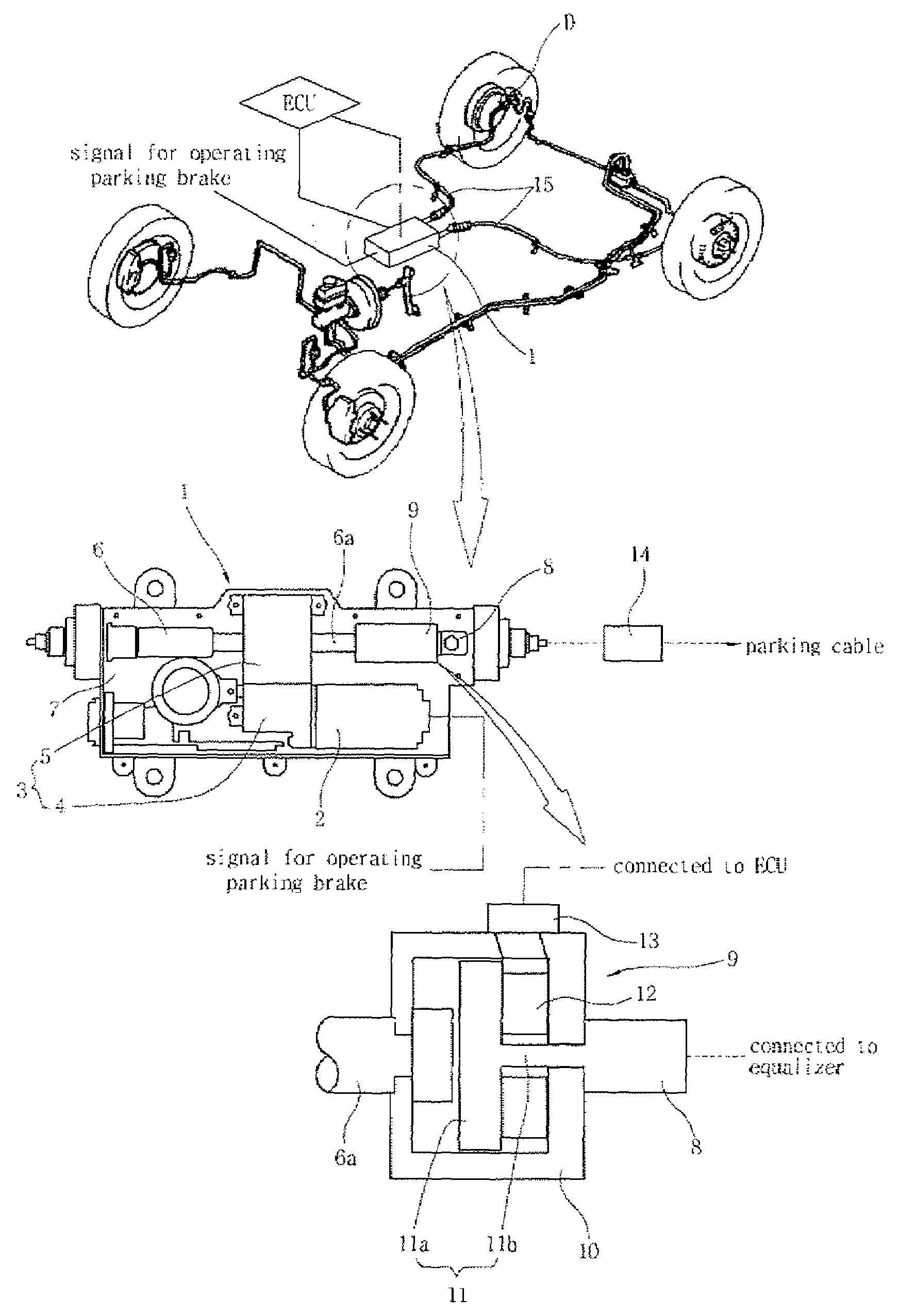
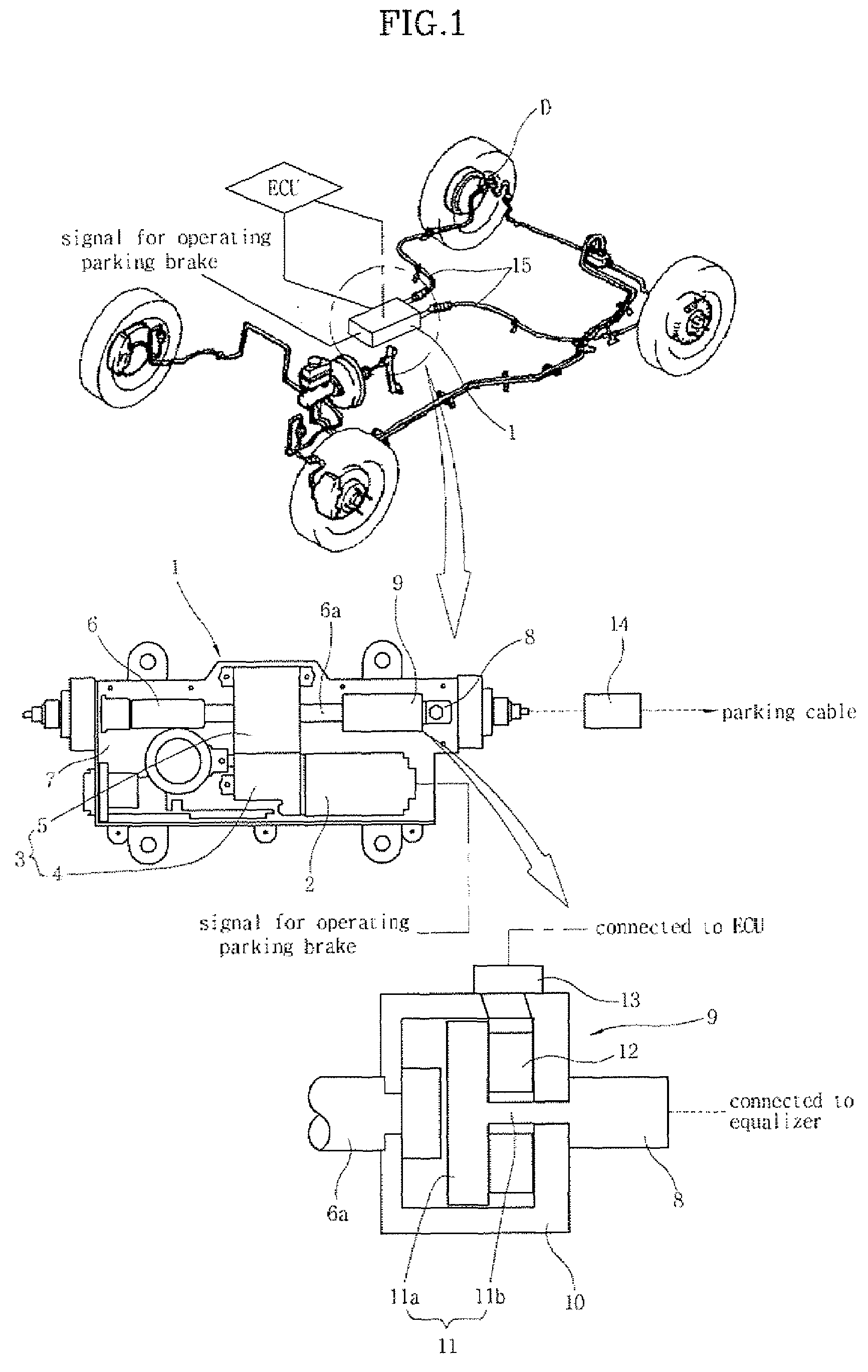
[0017]FIG. 1 is a schematic view of an electric parking brake for vehicles having an operating load measuring device, according to the present invention. As shown in the drawing, the electric parking brake of the present invention includes an actuating device 1, which provides a force for locking or unlocking the parking brake using power supplied by manipulation of a control button, and an equalizer 14, which is coupled at a first end thereof to the actuating device 1 and is coupled at a second end thereof to a parking cable 15 to pull or release the parking cable 15, which operates a braking device D of a wheel, in response to operation of the actuating device 1. The electric parking brake of the present invention further includes an operating load measuring unit 9, which measures operating load that pulls the equalizer 14 in the parking cable 15 a...


PUM


Abstract

An electric parking brake includes an actuating device, which provides a force to lock and unlock the parking brake using power supplied by manipulation of a control button, and an equalizer, which is coupled at a first end thereof to the actuating device and is coupled at a second end thereof to a parking cable to pull or release the parking cable, which operates a braking device of a wheel, depending on operation of the actuating device. The electric parking brake further includes an operating load measuring unit, which measures operating load that pulls the equalizer in the parking cable and sends the measured signal to an ECU that controls the actuating device.

Description

CROSS-REFERENCE TO RELATED APPLICATIONS[0001]The present application is based on, and claims priority from. Korean Application Serial Number 10-2006-0056825, filed on Jun. 23, 2006, the disclosure of which is hereby incorporated by reference herein in its entirety.FIELD OF THE INVENTION[0002]The present invention relates to parking brakes for vehicles and, more particularly to an electric parking brake for vehicles which measures an operating load using a piezoelectric sensor.BACKGROUND OF THE INVENTION[0003]Generally, when parking vehicles, users manipulate parking brakes to prevent the vehicles from undesirably moving before getting out of the vehicles.[0004]In such a parking brake, force applied to a parking cable when a parking brake lever is pulled is evenly transmitted to braking devices of wheels through an equalizer. The braking devices hold the respective wheels, thus preventing the vehicle from undesirably moving.[0005]As such, in the case where the wheels are braked by ma...

Claims


Application Information

Patent Timeline
Patent Type & Authority Applications(United States)
IPC IPC(8): B60T13/00
CPCB60T13/746B60T7/12
Inventor JEON, JAE-WOO
Owner HYUNDAI MOBIS CO LTD
Why Eureka
Try Eureka