Liquid crystal display device and method of driving same

a display device and liquid crystal technology, applied in the direction of instruments, static indicating devices, etc., can solve the problems of danger of liquid crystal burn-in, and achieve the effects of preventing burn-in or reducing flicker, preventing burn-in of display devices, and preventing burn-in or flicker reduction

Active Publication Date: 2009-05-14
NEC LCD TECH CORP
View PDF6 Cites 10 Cited by
  • Summary
  • Abstract
  • Description
  • Claims
  • Application Information

AI Technical Summary

Benefits of technology

[0020]In accordance with such a liquid crystal display device and method for driving the same, the signals between mutually adjacent subframes within the same frame may be reversed and output, thereby reversing the polarity of a sequential analog video signal, which is written to a liquid crystal panel, unconditionally in mutually adjacent subframe units into which the frame has been divided, thus enabling burn-in to be prevented.
[0021]Further, the signals in subframes corresponding to the same color are compared in each frame of a mutually adjacent first frame and second frame, and the polarity impressed upon a liquid crystal panel can be selected. Accordingly, the reversal or non-reversal of the polarity of a sequential analog video signal can be selected in units of mutually adjacent frames, and prevention of burn-in or reduction of flicker can be set as necessary. That is, if a change in the video signal is not detected between subframes of the same color between mutually adjacent frames, the polarity is made the same and flicker due to a change in polarity can be prevented. Further, if there is a change in the video signal between subframes of the same color, the polarity is reversed. As a result, if observed over an extended period of time, DC components are cancelled out and burn-in of the display device can be prevented.

Problems solved by technology

However, since the polarities of voltages in monochromatic images of the same color are always the same, a DC component tends to become superimposed upon the video signal, which is written to the pixels, owing to a slight computational error.
Hence there is the danger of liquid crystal burn-in.

Method used


Image

  • Liquid crystal display device and method of driving same
  • Liquid crystal display device and method of driving same
  • Liquid crystal display device and method of driving same

Examples


first exemplary embodiment

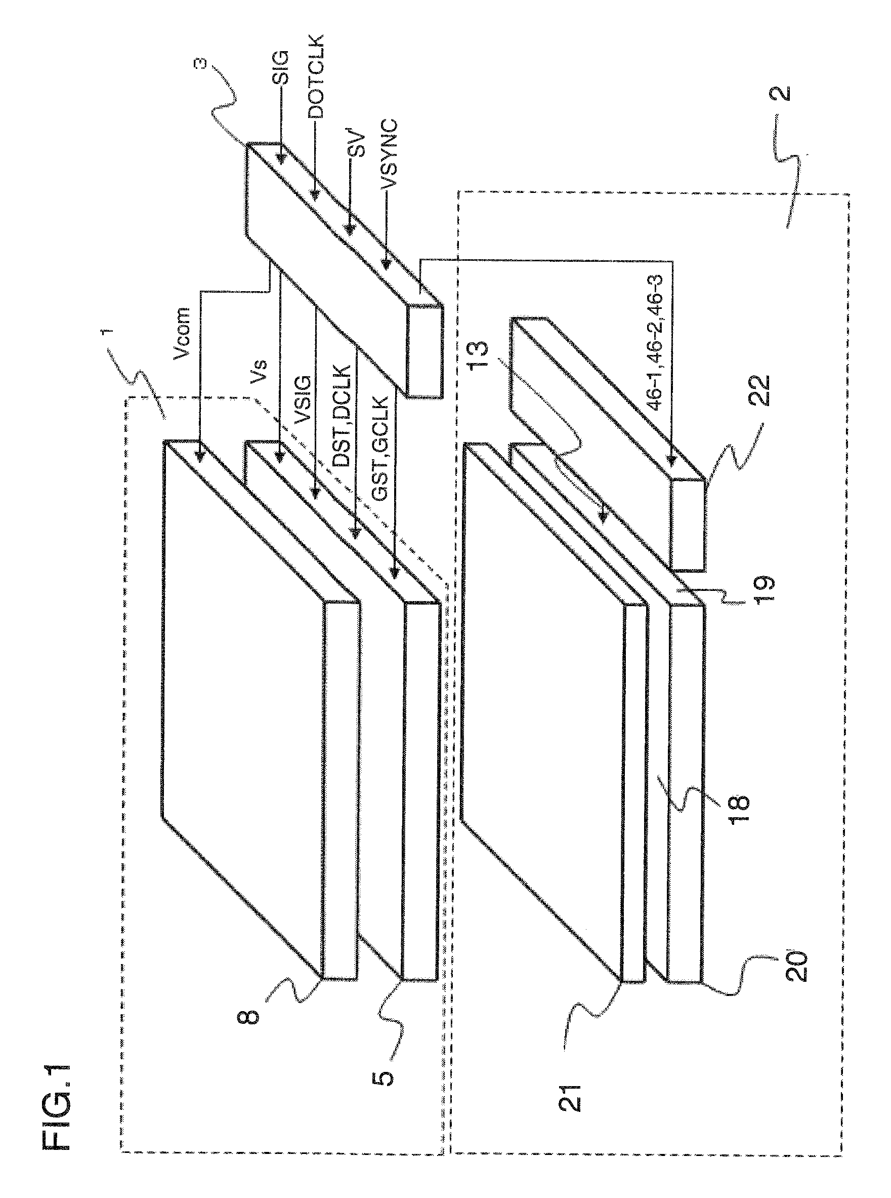
[0039]FIG. 1 is a diagram illustrating a configuration of a liquid crystal display device according to a first exemplary embodiment of the present invention. The liquid crystal display device according to the present invention is a color field-sequential liquid crystal display device having a liquid crystal panel, a planar light-source unit that emits light toward the liquid crystal panel and a signal processor connected to the liquid crystal panel and planar light-source unit. More specifically, as shown in FIG. 1, the liquid crystal display device includes a liquid crystal panel 1 having one surface for displaying video; a backlight 2 serving as a planar light source disposed on the non-display side of the liquid crystal panel 1, namely on the other surface thereof; and a signal processor 3 for supplying the liquid crystal panel 1 and backlight 2 with signals.

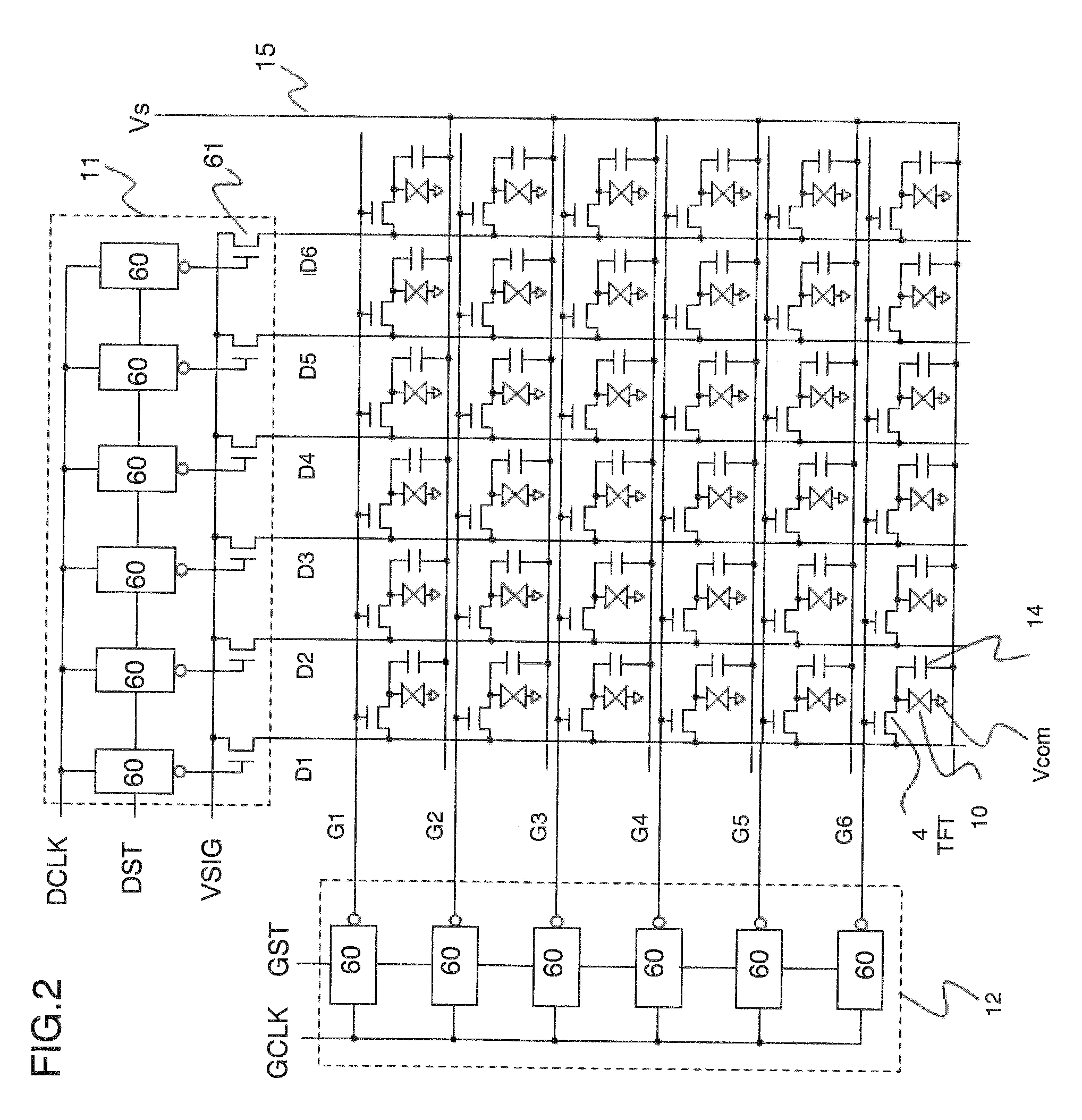
[0040]The liquid crystal panel 1 comprises transparent substrates 5 and 8. As illustrated in FIG. 2, the transparent substr...

second exemplary embodiment

[0080]In the first exemplary embodiment, one frame is divided into three subframes in which monochromatic video of the respective colors R (red), G (green) and B (blue) is displayed. However, the number of divisions of one frame may be changed. A second exemplary embodiment of the present invention provides a liquid crystal display device in which one frame is divided into four subframes. Components identical with those of the first exemplary embodiment are designated by like reference characters and need not be described again.

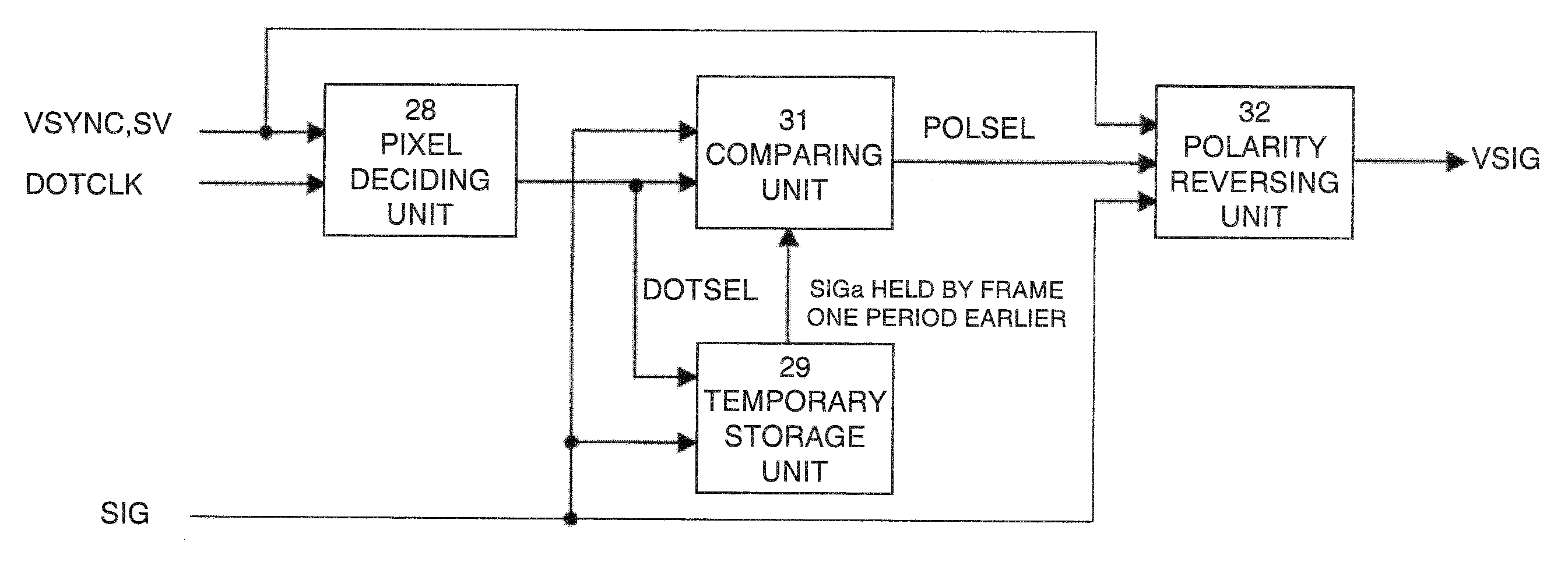
[0081]FIG. 9 is a circuit diagram of a pixel deciding unit according to the second exemplary embodiment of the present invention. Components in FIG. 9 identical with those of FIG. 4 are designated by like reference characters. The pixel deciding unit 28 shown in FIG. 9 is obtained by adding a flip-flop FF5 and a 2-input AND gate AND1 to the arrangement of FIG. 4. The flip-flop FF5 receives the signal 33-1, which switches between high and low every subframe pe...


PUM


Abstract

A color field-sequential liquid crystal display device comprising: a liquid crystal panel; a planar light-source unit for emitting light toward the liquid crystal panel; and a signal processor connected to the liquid crystal panel and to the planar light-source unit; wherein the signal processing includes: a comparing unit that compares video signals included in subframes of at least one identical color in each frame of two mutually adjacent video frames; and a polarity reversing unit that reverses the polarities of video signals in mutually adjacent subframes within the same frame, deciding whether or not to reverse the polarities of all video signals of one frame based upon the result of the comparison by the comparing unit, and outputting a video signal having the decided polarity to the liquid crystal panel.

Description

REFERENCE TO RELATED APPLICATION[0001]This application is based upon and claims the benefit of the priority of Japanese patent application No. 2007-295732, filed on Nov. 14, 2007, the disclosure of which is incorporated herein in its entirety by reference thereto.TECHNICAL FIELD[0002]This invention relates to a liquid crystal display device and to a method for driving the same. More particularly, the invention relates to a color field-sequential liquid crystal display device and to a method for driving this device.BACKGROUND[0003]Methods for colorizing a display device mainly employ a method based upon spatial division and a method based upon time division. Further, there are also display devices that use a combination of both of these methods. Examples of colorization using spatial division are a delta-shaped spatial array of phosphors of a plurality of colors in a CRT and a spatial array of color filters in a liquid crystal display. Colorization using time division usually is refe...

Claims


Application Information

Patent Timeline
Patent Type & Authority Applications(United States)
IPC IPC(8): G09G3/36
CPCG09G3/3614G09G2310/0235G09G2320/0266G09G2320/0242G09G2320/0247G09G2320/0204
Inventor MASUMURA, KAZUNORI
Owner NEC LCD TECH CORP
Why Eureka
Try Eureka