Driving device for backlight module and display device thereof

a backlight module and display device technology, applied in the direction of electric variable regulation, process and machine control, instruments, etc., can solve the problems of increasing serious problems and damage to the current control unit b>30/b>, so as to avoid reduce the power consumption of the display device. , the effect of avoiding damage to the current control uni

Inactive Publication Date: 2009-05-14
CHUNGHWA PICTURE TUBES LTD
View PDF3 Cites 46 Cited by
  • Summary
  • Abstract
  • Description
  • Claims
  • Application Information

AI Technical Summary

Benefits of technology

[0024]The present invention employs a power conversion circuit to provide an adjustable voltage to the backlight module, and employs a PWM generator to monitor an output voltage of the backlight module for regulating a PWM signal genera

Problems solved by technology

However, when the LED 107 is being operated, it inevitably liberates heat and causes Ta to rise, causing several problems.
In addition, the increased forward current If even increases the load of the drivin

Method used


Image

  • Driving device for backlight module and display device thereof
  • Driving device for backlight module and display device thereof
  • Driving device for backlight module and display device thereof

Examples


first embodiment

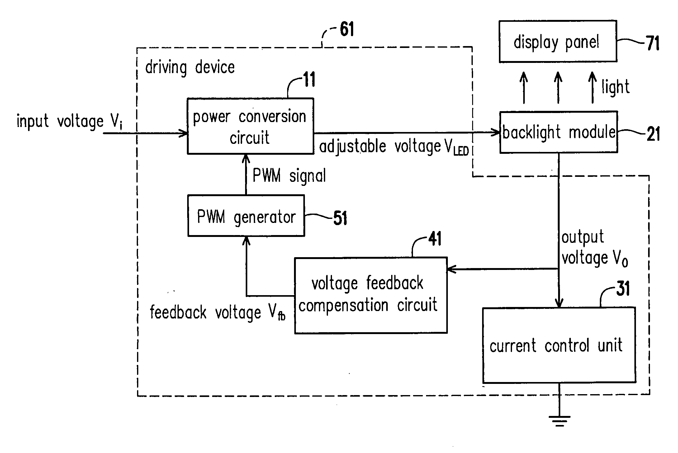
[0037]FIG. 3 is a schematic diagram illustrating a display device according to the present invention. Referring to FIG. 3, there is shown a display device including a driving device 61 for a backlight module, a backlight module 21, and a display panel 71. According to the embodiment, the display panel 71 is exemplified with an LCD panel. The driving device 61 for the backlight module 21 includes a power conversion circuit 11, a PWM generator 51, a current control unit 31, and a voltage feedback compensation circuit 41. The power conversion circuit 11 converts an input voltage Vi into an adjustable voltage VLED. The PWM generator 51 regulates a PWM signal for adjusting the adjustable voltage VLED. The backlight module 21 receives the adjustable voltage VLED, and emits light correspondingly. The current control unit 31 is adapted for controlling a current flowing through the backlight module 21.

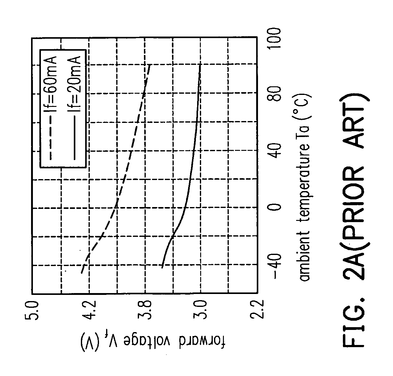
[0038]Characteristics of the backlight module 21 is subject to be affected by Ta. According...

second embodiment

[0056]Those of ordinary skill in the art may provide the reference voltage Vref to the PWM generator 51 in other ways according to the practical requirement. FIG. 10 is a schematic diagram illustrating a display device having a function of adjusting a reference voltage according to the present invention. Referring to FIG. 10, there is shown voltage dividing resistors R3 and R4 serving adjustable resistors for illustrating the present invention, in other embodiments, fixed resistors may be used. The voltage dividing resistor R3 has a first terminal coupled to an input voltage Vi, and a second terminal coupled to a first terminal of the voltage dividing resistor R4 and the PWM generator 51, and a second terminal of the voltage dividing resistor R4 are coupled to a zero potential voltage (in other embodiments, other potentials may be coupled to). The voltage dividing resistors R3 and R4 are adapted for providing the reference voltage Vref to the PWM generator 51. In such a way, the PWM...


PUM


Abstract

A display device and a driving device for driving a backlight module are provided. The driving device includes a power conversion circuit (PCC), a PWM generator, a current control unit (CCU) and a voltage feedback compensation circuit (VFCC). The PCC is used for converting an input voltage into an adjustable voltage supplied to the backlight module. The CCU is used for controlling current flowing through the backlight module. The VFCC is used for receiving an output voltage from the backlight module and providing a feedback voltage to the PWM generator, so that the PWM generator adjusts the adjustable voltage accordingly. Therefore, the driving device submitted by the present invention can be reduced the entire power consumption of the display device and further avoided the current control unit happened damage also.

Description

CROSS-REFERENCE TO RELATED APPLICATION[0001]This application claims the priority benefit of Taiwan application serial no. 96142186, filed on Nov. 8, 2007. The entirety of the above-mentioned patent application is hereby incorporated by reference herein and made a part of specification.BACKGROUND OF THE INVENTION[0002]1. Field of the Invention[0003]The present invention generally relates to a backlight module for a display device and a display panel, and more particularly, to a device supplying a voltage to a backlight module.[0004]2. Description of Related Art[0005]As video technology is being developed, liquid crystal display (LCD) devices are widely used as displaying screens for consumer products such as cellular phones, laptop computers, personal computers, and personal digital assistants (PDAs). An LCD panel does not emit light by itself. As such, it needs a backlight module disposed thereunder to provide plane light source so that the LCD panel can display images.[0006]FIG. 1 ...

Claims


Application Information

Patent Timeline
IPC IPC(8): G09G3/36H05B41/36
CPCG09G3/3406G09G2320/041G09G2320/0633H05B33/0851G09G2330/02G09G2330/021G09G2330/04G09G2320/064H05B45/18
Inventor CHEN, HUNG-HSIANGCHU, YI-NAN
Owner CHUNGHWA PICTURE TUBES LTD
Why Eureka
Try Eureka