Thyristor power control circuit

a power control circuit and thyristor technology, applied in the field of electromechanical circuits, can solve the problems of flickering at the led load, erratic performance of the power converter b>228/b>, and the inability of the power converter to provide resistive damping to the emi, so as to prevent flickering

Active Publication Date: 2009-05-14
STMICROELECTRONICS SRL
View PDF14 Cites 46 Cited by
  • Summary
  • Abstract
  • Description
  • Claims
  • Application Information

AI Technical Summary

Benefits of technology

[0007]A thyristor power control circuit prevents EMI from leaving a power converter. The power control circuit also maintains a holding current in the thyristor to prevent flickering at a load. The power control circuit includes a thyristor configured to receive an input AC voltage, and responsive to a gate pulse generates a modified AC voltage. A rectifier receives the modified AC voltage and generates a rectified DC voltage. A power converter coupled to the rectifier receives the rectified DC voltage and generates a controlled output current. A damp

Problems solved by technology

As discussed before, the power converter 228 does not provide the resistive damping to the EMI.
Lacking the holding current, the thyristor 204 turns O

Method used


Image

  • Thyristor power control circuit
  • Thyristor power control circuit
  • Thyristor power control circuit

Examples


Embodiment Construction

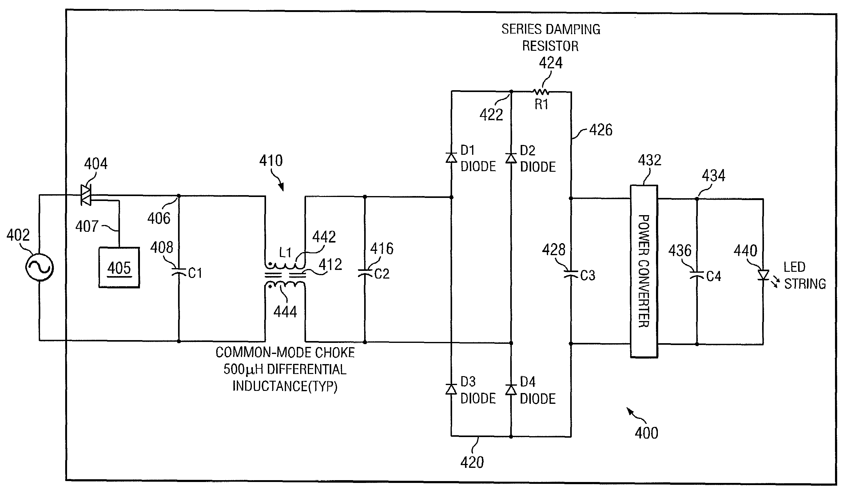
[0017]FIG. 4 illustrates a thyristor power control circuit 400 in accordance with an example embodiment. The circuit 400 includes an AC voltage source 402 connected to a thyristor 404. A pulse generator circuit 405 applies a periodic pulse at a gate terminal 407 of the thyristor 404. Due to a switching action, the thyristor 404 generates a modified AC voltage at a terminal 406. The modified AC voltage is passed through an input filter 410 filter comprising capacitors 408, 416 and a common mode choke 412 having a first and a second winding 442 and 444, respectively. A full bridge rectifier 420 comprising diodes D1-D4 rectifies the modified AC voltage into a DC voltage at the rectifier output terminal 422.

[0018]A series damping resistor 424 is connected to the rectifier output terminal 426. The series damping resistor 424 is also connected to a capacitor 428. A high-frequency pulsed current drawn by a power converter circuit 432 is filtered by the capacitor 428. The output of the capa...


PUM


Abstract

A thyristor power control circuit reduces EMI and maintains a holding current in the thyristor to prevent flickering at a load. The power control circuit includes a thyristor configured to receive an input AC voltage, and responsive to a gate pulse generates a modified AC voltage. A rectifier receives the modified AC voltage and generates a rectified DC voltage. A power converter coupled to the rectifier receives the rectified DC voltage and generates a controlled output current. A damping circuit coupled to an output terminal of the rectifier includes a damping resistor for maintaining the holding current in the thyristor during an ON period of the thyristor. The damping circuit includes a first capacitor coupled in series to the damping resistor and a diode coupled in parallel to the damping resistor. The diode enables the first capacitor to discharge without causing power loss at the damping resistor.

Description

CROSS-REFERENCE TO RELATED APPLICATIONS[0001]Pursuant to 35 U.S.C. § 119 (e), this application claims priority from, and hereby incorporates by reference for all purposes, U.S. Provisional Patent Application Ser. No. 60 / 927,687, entitled METHOD FOR MAKING A POWER CONVERTER LED DRIVER DIMMABLE WITH A COMMON THYRISTOR DIMMER, and filed May 4, 2007.FIELD OF THE INVENTION[0002]The invention relates to electronic circuits, and more particularly the invention relates to a thyristor power control circuit.BACKGROUND OF THE INVENTION[0003]Thyristor dimmer circuits are frequently used to control incandescent lamps, LED lamps and other loads. FIG. 1A illustrates a thyristor dimmer circuit 100. The thyristor dimmer circuit 100 includes a triac-type thyristor 104 connected to an AC voltage source 112. The thyristor 104 is also connected in series to an inductor 120 and to an incandescent lamp 108. A capacitor 124 is connected in parallel to the thyristor 104 and to the inductor 120. A pulse gene...

Claims


Application Information

Patent Timeline
IPC IPC(8): H02M1/12
CPCH02M7/15H05B33/0815H05B33/0809H02M2001/007H05B45/3725H02M1/007
Inventor STAMM, THOMASBOTHRA, VIPINWONG, VEE SHING
Owner STMICROELECTRONICS SRL
Why Eureka
Try Eureka