Ethernet switching and forwarding method, system and apparatus

Active Publication Date: 2009-05-14
HUAWEI TECH CO LTD
View PDF14 Cites 39 Cited by
  • Summary
  • Abstract
  • Description
  • Claims
  • Application Information

AI Technical Summary

Benefits of technology

[0044]With the above solutions of the Ethernet switching and forwarding method, system and apparatus according to the embodiments of the invention applied in a telecommunication network, in view of full compatibility with the traditional Ethernet technical framework, some specific demands in the telecommunication network may be satisfied. For example, flexible and abundant forwarding modes are provided for satisf

Problems solved by technology

These requirements are in conflict with the basic Ethernet technical framework.
The solution with such a mechanism is disadvantageous in that: the MAC address belongs to a user terminal and thus is not trustworthy because numerous network attacks are made through MAC address spoofing, such as a Broadband Remote Access Server (BRAS) address spoofing, message redirecting, which may interfere greatly with a service of a normal user; the learning of the MAC address may consume a MAC address space table, which may result in a scalability problem of an aggregation layer device, for example, currently the aggregation layer device is required to be provided with a MAC address table entry space of at least 32K; and the MAC address table is vulnerable due to a Deny of Service (DoS) attack of the MAC address.
Furthermore, the incredibility of the MAC address may also result in disability of identifying or locating a user according to the MAC address.
However this solution has the following drawbacks: the network security and service isolation cannot be achieved ideally with the existing VLAN technology, because the service intercommunication between users in a VLAN, which is typically prohibited in a telecommunication network, may be implemented with the flooding and MAC address auto-learning mechanism; furthermore, the MAC/IP spoofing still may be present in the VLAN; in addition, the problem of extendibility may occur in the case where the VLAN identifier is used as a service connection identifier between the AN and the BBNG primarily in that a service connection between the AN the BBNG is expected to carr

Method used


Image

  • Ethernet switching and forwarding method, system and apparatus
  • Ethernet switching and forwarding method, system and apparatus
  • Ethernet switching and forwarding method, system and apparatus

Examples


Embodiment Construction

[0049]Embodiments of the invention are described in details as follows.

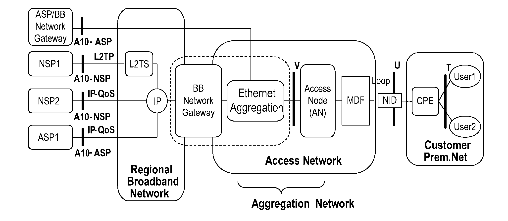
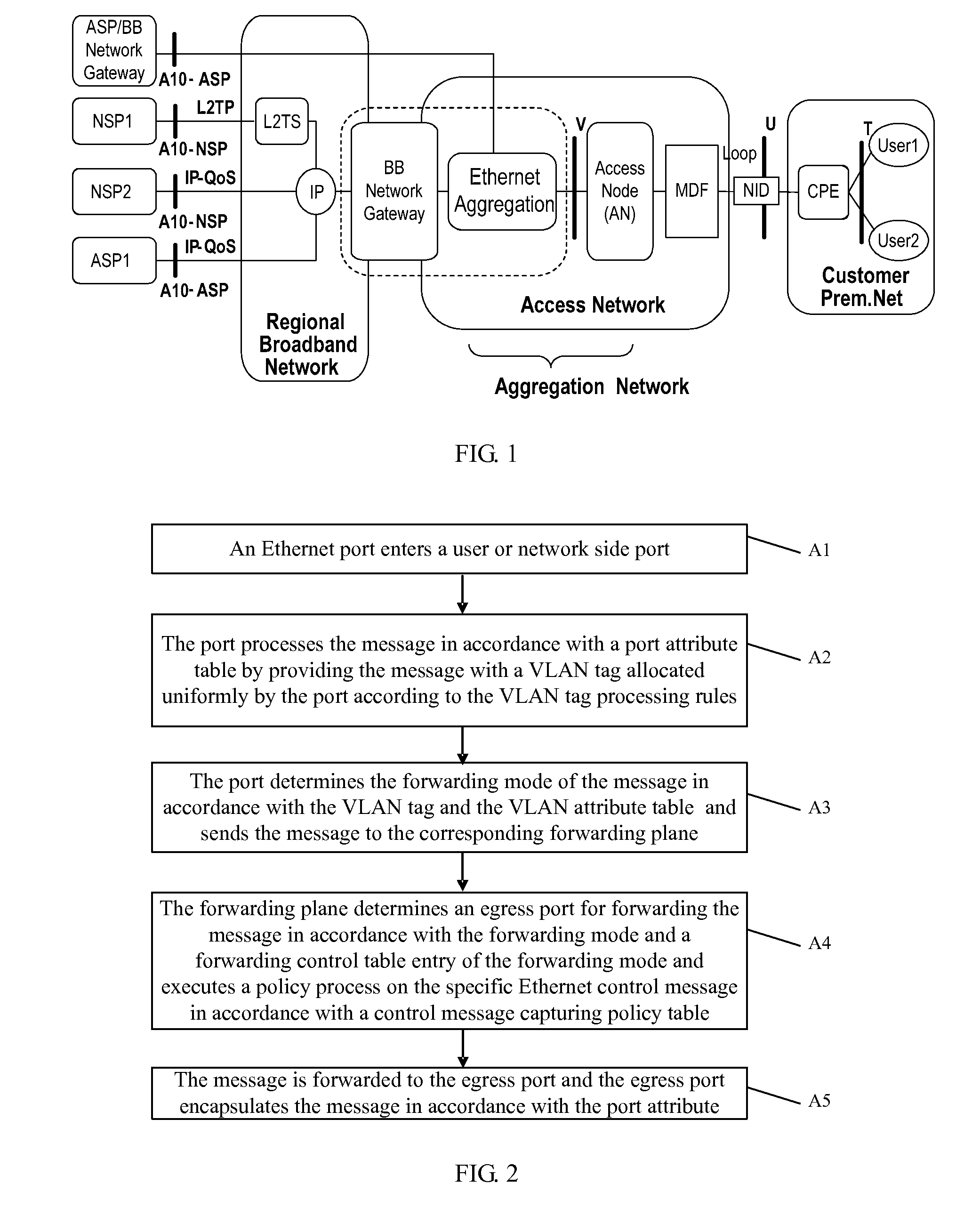
[0050]In view of demands in a telecommunication operation network, the existing Ethernet forwarding mode is improved with various definitions made based on the existing Ethernet network architecture according to an embodiment of the invention, and thus can be applied to an access device and an Ethernet aggregation device in telecommunication access and aggregation networks, and to an Ethernet forwarding and switching chip as well.

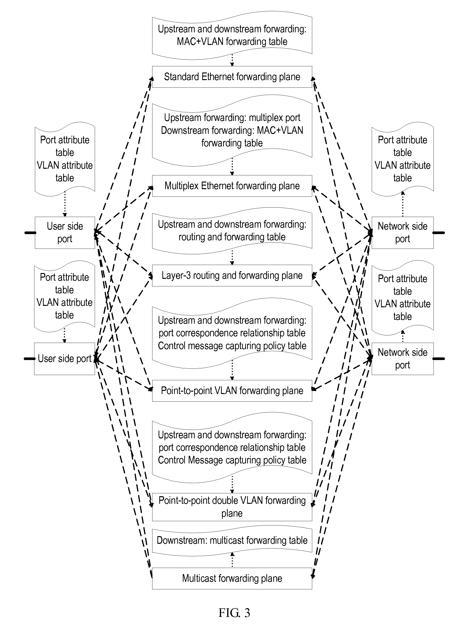
[0051]Accordingly, an Ethernet switching and forwarding method is provided according to an embodiment of the invention. The method includes the forwarding modes of standard Ethernet forwarding, multiplex Ethernet forwarding, layer-3 routing and forwarding, across-VLAN multicast forwarding, point-to-point VLAN forwarding, transparent point-to-point VLAN forwarding, point-to-point double VLAN forwarding, and transparent point-to-point double VLAN forwarding, which will be described in deta...


PUM


Abstract

An Ethernet switching and forwarding method, and at least one Ethernet forwarding mode of standard Ethernet forwarding, multiplex Ethernet forwarding, layer-3 routing and forwarding, across-VLAN multicast forwarding plane, point-to-point VLAN forwarding, or point-to-point double VLAN forwarding. The method includes: an Ethernet message entering a user side port or a network side port; processing, by the port, the message to provide the message with a VLAN tag allocated uniformly by the port; determining, by the port, a forwarding mode for the message and sending the message to a corresponding forwarding plane; determining, by the forwarding plane, an egress port of the message and processing the specific Ethernet control message in accordance with a control message capturing policy table; and forwarding the message to the egress port and encapsulating the message in accordance with an attribute table of the egress port.

Description

CROSS-REFERENCE TO RELATED APPLICATION[0001]This application is a continuation of International Patent Application No. PCT / CN2007 / 001874, filed Jun. 14, 2007, which claims priority to Chinese Patent Application No. 200610061219.8, filed Jun. 16, 2006, both of which are hereby incorporated by reference in their entirety.FIELD OF THE INVENTION[0002]The present invention relates to an application of Ethernet in a telecommunication network and, in particular, to an Ethernet switching and forwarding method, system and apparatus.BACKGROUND OF THE INVENTION[0003]The transition of a telecommunication operation network toward an IP-oriented network has been predominant along with development and applications of IP technologies, and the Ethernet, which acts as an optimal bearer mechanism for IP, has also been increasingly popular in the telecommunication operation network. Particularly, an access and aggregation network of the telecommunication operation network is typically based on informat...

Claims


Application Information

Patent Timeline
IPC IPC(8): H04L12/28
CPCH04L12/4645H04L49/354H04L49/351H04L12/467
Inventor CHANG, YUE
Owner HUAWEI TECH CO LTD
Why Eureka
Try Eureka