X-ray ct apparatus

a ct and x-ray technology, applied in the field of x-ray ct (computed tomography) apparatus, can solve the problems of large problem of x-ray needless exposure, hard control of image quality, etc., and achieve the effect of reducing x-ray dose, optimum image quality, and optimum image quality

Inactive Publication Date: 2009-05-14
GE MEDICAL SYST GLOBAL TECH CO LLC
View PDF14 Cites 25 Cited by
  • Summary
  • Abstract
  • Description
  • Claims
  • Application Information

AI Technical Summary

Benefits of technology

[0005]On the other hand, the X-ray CT apparatus having the multi-row X-ray detector or the X-ray CT apparatus based on the two-dimensional X-ray area detector typified by the flat panel has a tendency that as a cone angle of an X-ray cone beam becomes great, the problem of X-ray needless exposure becomes larger. It is therefore necessary to perform photography at a more reduced X-ray dose even upon photographing each tomographic image indicative of the X-ray tube voltage dependent information of each material constituting the subject. It is also necessary to photograph under an imaging condition that can obtain the optimum image quality.
[0006]Therefore, an object of the present invention is to provide an X-ray CT apparatus capable of obtaining each tomographic image indicative of X-ray tube voltage dependent information of a subject with the optimum image quality by less reduced exposure.

Problems solved by technology

However, the process of bringing the information about the difference between the dependencies of the X-ray absorption coefficients on the X-ray tube voltages was a process hard to control the quality of each image obtained by a process for performing weighted subtraction on the tomographic images at the X-ray tube voltages and control noise of the image.
On the other hand, the X-ray CT apparatus having the multi-row X-ray detector or the X-ray CT apparatus based on the two-dimensional X-ray area detector typified by the flat panel has a tendency that as a cone angle of an X-ray cone beam becomes great, the problem of X-ray needless exposure becomes larger.

Method used


Image

  • X-ray ct apparatus
  • X-ray ct apparatus
  • X-ray ct apparatus

Examples


Embodiment Construction

[0047]The present invention will hereinafter be described in further detail by embodiments illustrated in the drawings. Incidentally, the present invention is not limited thereby.

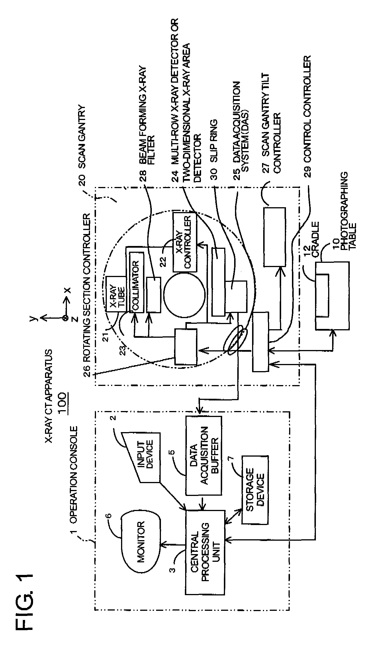
[0048]FIG. 1 is a configuration block diagram of an X-ray CT apparatus according to one embodiment of the present invention. The X-ray CT apparatus 100 is equipped with an operation console 1, a photographing table 10 and a scan gantry 20.

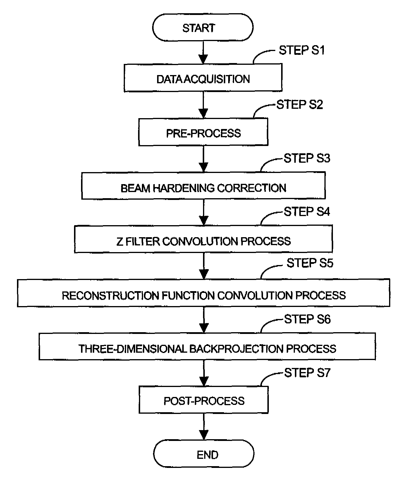
[0049]The operation console 1 is equipped with an input device 2 which receives an input from an operator, a central processing unit 3 which executes a pre-process, an image reconstructing process, a post-process, etc. a data acquisition buffer 5 which acquires or collects X-ray detector data acquired by the scan gantry 20, a monitor 6 which displays a tomographic image image-reconstructed from projection data obtained by pre-processing the X-ray detector data, and a storage device 7 which stores programs, X-ray detector data, projection data and X-ray tomographic images t...


PUM


Abstract

The present invention provides an X-ray CT apparatus capable of obtaining each tomographic image indicative of X-ray tube voltage dependent information of a subject with the optimum image quality by less reduced exposure. The X-ray CT apparatus includes device for setting a plurality of X-ray tube voltages and sets imaging conditions used in the photography using the respective X-ray tube voltages in such a manner that respective image noise of tomographic images photographed at the X-ray tube voltages become substantially identical to one another. The setting of the imaging conditions is the setting of X-ray tube currents. The X-ray tube currents are set based on geometrical characteristic amounts of the subject determined from each scout image in such a manner that the respective image noise of the tomographic images photographed at the plurality of X-ray tube voltages become substantially identical to one another.

Description

CROSS REFERENCE TO RELATED APPLICATIONS[0001]This application claims the benefit of Japanese Patent Application No. 2007-290817 filed Nov. 8, 2007, which is hereby incorporated by reference in its entiretyBACKGROUND OF THE INVENTION[0002]The subject matter disclosed herein relates to a technique of a medical X-ray CT (Computed Tomography) apparatus or an industrial X-ray CT apparatus.[0003]In an X-ray CT apparatus having a multi-row X-ray detector or an X-ray CT apparatus based on a two-dimensional X-ray area detector of a matrix structure typified by a flat panel, there has heretofore been a technique which photographs tomographic images at a plurality of X-ray tube voltages as shown in FIG. 7 and brings information about a difference between the dependencies of X-ray absorption coefficients of materials constituting a subject on the X-ray tube voltages into imaging, based on the tomographic images.BRIEF DESCRIPTION OF THE INVENTION[0004]However, the process of bringing the informa...

Claims


Application Information

Patent Timeline
Patent Type & Authority Applications(United States)
IPC IPC(8): A61B6/00
CPCA61B6/032A61B6/4085A61B6/542A61B6/488A61B6/466
Inventor NISHIDE, AKIHIKOSASAKI, KOSUKEHORIUCHI, TETSUYA
Owner GE MEDICAL SYST GLOBAL TECH CO LLC
Why Eureka
Try Eureka