Two-Part Dental Implant

a dental implant and two-part technology, applied in dental implants, dental surgery, medical science, etc., can solve the problems of not meeting the above-indicated demands to the desired degree, the transition between the two implant portions, and the known two-part dental implants that cannot meet the above-indicated demands, so as to achieve less compressibility and improve body compatibility

Active Publication Date: 2009-05-14
MEHROF IMPLANT TECH GMBH
View PDF16 Cites 26 Cited by
  • Summary
  • Abstract
  • Description
  • Claims
  • Application Information

AI Technical Summary

Benefits of technology

[0035]In addition it may be advantageous for surfaces of the implant or its constituent parts, in particular the outwardly directed surface of the sealing body, to be polarized in order to achieve better body compatibility. Polarization provides that the adjoining tissue such as for example bone and gums do not or cannot demonstrate rejection behavior in relation to the coating.
[0036]In regard to a possibly partially coated sealing body it is desirable if the coated surfaces do not have any sharp edges. Rather, all coated edges should be rounded in order to prevent the coating from flaking off upon deformation of the sealing body.
[0037]It is advantageous if the elastic material of the sealing body is elastically stretchable or compressible by at least 5%, better by more than 20%. In an embodiment, by way of example, the spacing, which is predetermined by the abutment surfaces, between the mutually facing surfaces of the two implant portions is 250 μm so that the seal involves a nominal dimension of 250 μm. In this case the sealing body should be made for example 50 μm over the nominal dimension (250 μm) of the seal so that after assembly a compression of 50 μm (20% compression) already occurs. Those values represent an ideal dimension that it is sought to achieve. The structural height of the seal should be as small as possible in order for aesthetic reasons not to give away structural height for the later tooth crown; in particular dimensions between 0.1 mm and 3 mm are considered as the nominal dimension. In terms of dimensioning, it is crucial that the seal, even under the effect of mastication forces, is deformed only in the range of elastic deformability thereof and also always remains compressed by a minimum amount in partial regions, for example in the event of a lateral loading. Thus, when the implant is assembled, the sealing body is compressed only by the necessary degree so that the implant-abutment connection ensures sealing integrity under all possible circumstances. The degree of compression is dependent on the material and the thickness of the material, when using a greater structural height for the seal the compressibility of the material can turn out to be less in order to compensate for the movements in the sealing region.
[0038]For a sealing body which expands when heat is involved, in particular plastic materials with a high coefficient of thermal expansion of more than 75×10−6 / K at 20° are advantageous.
[0039]Preferably at least one outside surface of the sealing body, which surface forms the outside surface of the implant, is coated with a metal or ceramic layer in the manner described hereinbefore, in which case the metal-parylene or ceramic layer prevents bacteria from penetrating into seal components which are covered by the metal or ceramic layer. A nano coating, for example with titanium particles, is particularly suitable. The sealing surface itself can directly consist of a biocompatible plastic material or can be coated in the above-mentioned manner. In particular titanium, silver or gold, optionally also in the form of a constituent of an alloy, are considered as the material for the metal layer. All surface materials of the seals are mouth-resistant and sterilizable and do not absorb water or absorb water only to a very slight degree.
[0040]Besides elastic plastic material the sealing body may also include a metal spring or a separate plastic spring element of another plastic material, such as for example PEEK. The spring element can be in the form for example of a plate spring or a ring of a u-shaped, inwardly open cross-section and ensures permanent elasticity and stressing force for the sealing body. A metal spring can be advantageous in particular in relation to a sealing body in which the elastic plastic material at least partially comprises polytetrafluoroethylene (PTFE, Teflon), polypropylene (PP) or also polyetheretherketone (PEEK).

Problems solved by technology

Known two-part dental implants do not satisfy the above-indicated demands to the desired degree.
A particular problem in many known two-part implants is the transition between the two implant portions.

Method used


Image

  • Two-Part Dental Implant
  • Two-Part Dental Implant
  • Two-Part Dental Implant

Examples


Embodiment Construction

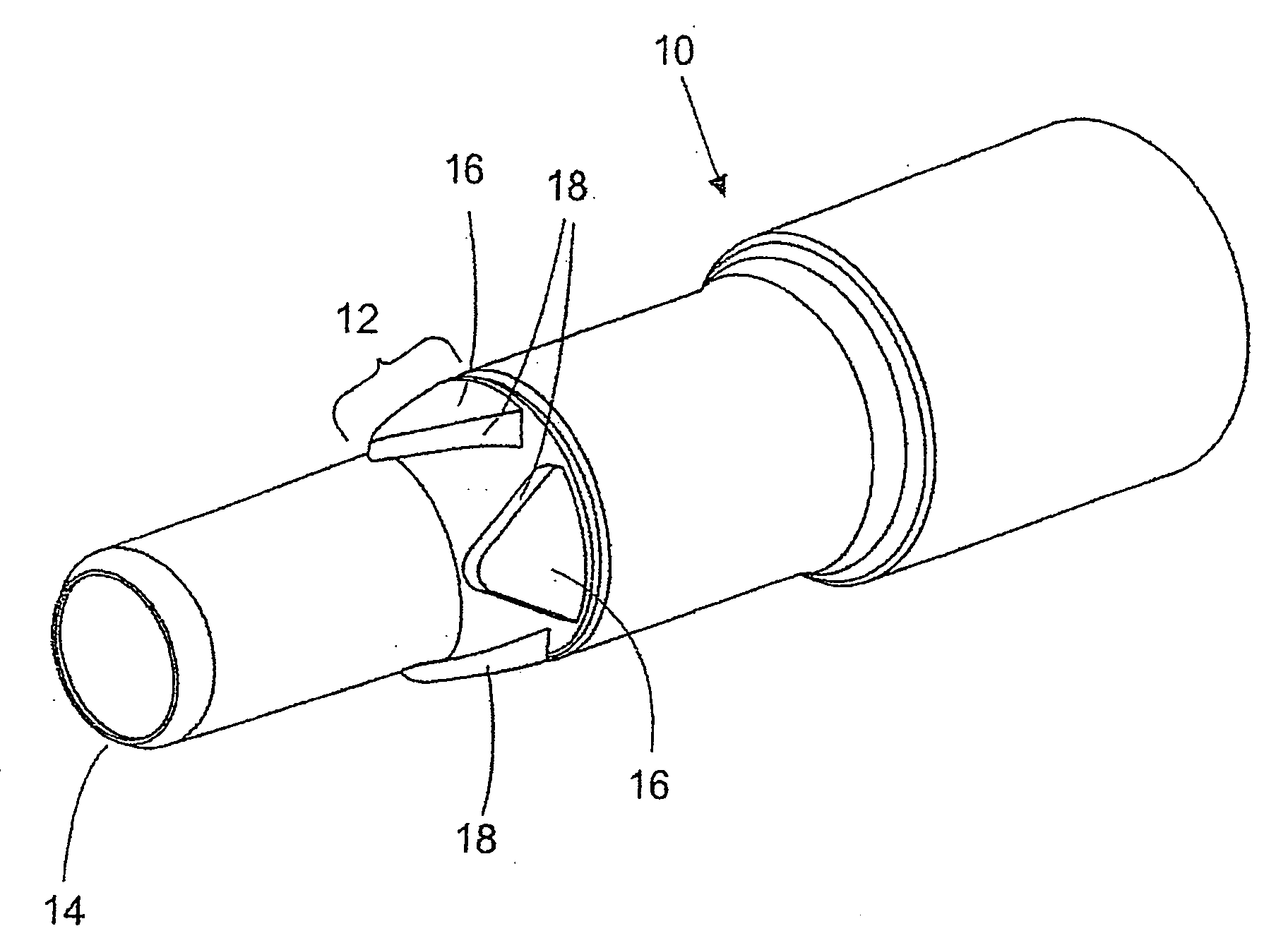
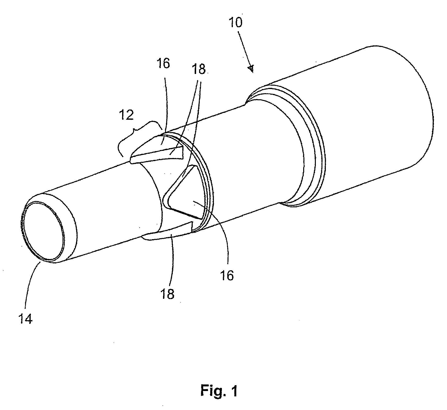
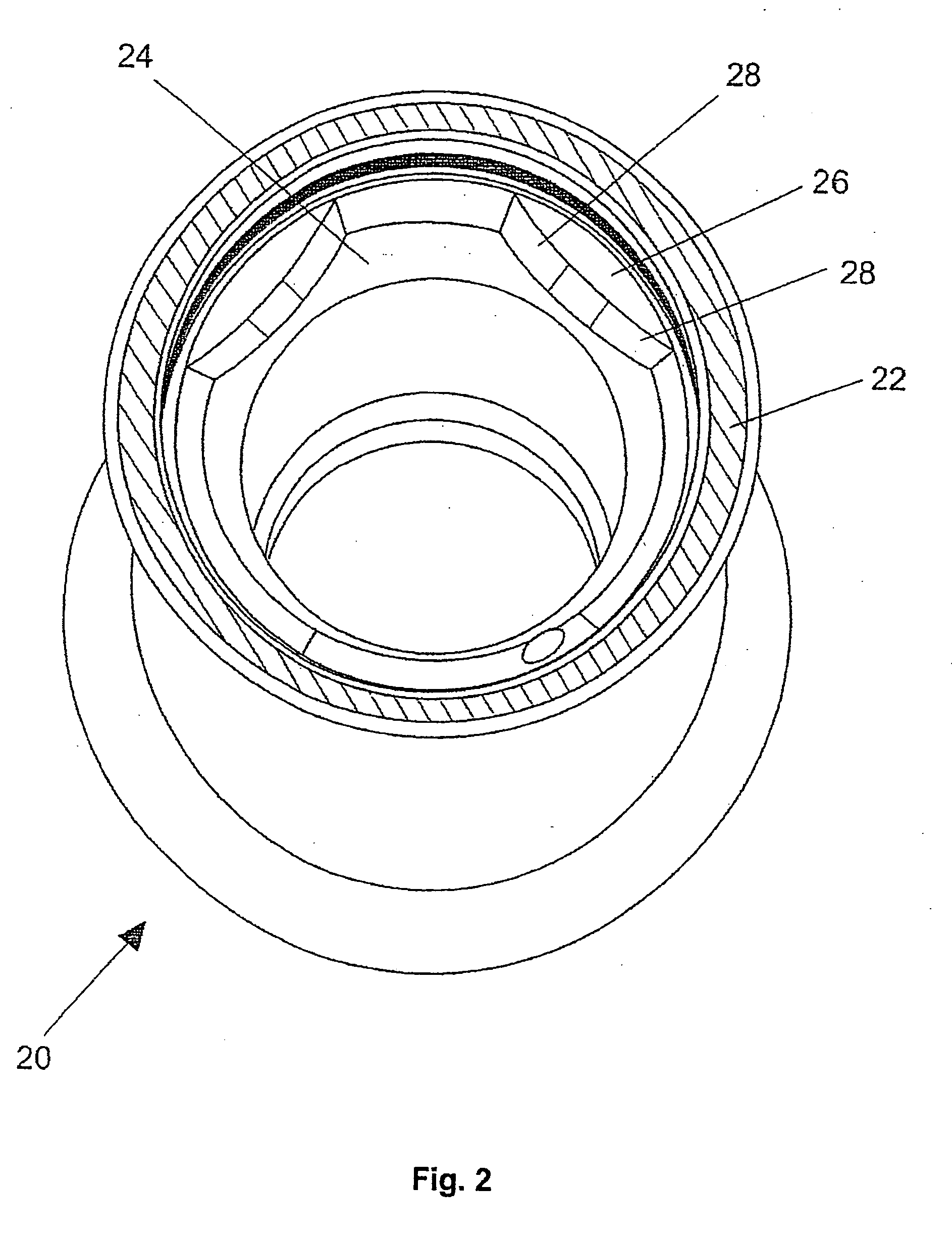
[0131]In the two-part dental implant shown in the specific embodiments a proximal implant portion is formed by a tooth structure stem portion 10 and a distal implant portion is formed by a distal stem portion 20.

[0132]As the perspective view of the tooth structure stem portion 10 shown in FIG. 1 illustrates, it has a longitudinal part 12 of a conical basic geometry which narrows towards the distal end 14 of the tooth structure stem portion 10. The cone angle is 10°. In the region of that conical longitudinal part 12 the tooth structure stem portion 10 has a total of four v-shaped projections 16 which face with their tips towards the distal end 14 of the tooth structure stem portion 10. The four v-shaped projections 16 act as triangular prongs and are symmetrical and are arranged at equal spacings from each other around the periphery of the conical longitudinal part 12 of the tooth structure stem portion 10. That affords eight flank surfaces 18 which face inclinedly towards the dista...


PUM


Abstract

A two-part dental implant includes distal and proximal implant portions which in an interconnected condition at least indirectly adjoin each other at a connecting location and have mutually facing surfaces in the region of the connecting location. A sealing body is provided between the mutually facing surfaces of the distal and proximal implant portions. The sealing body has sealing surfaces which face towards the mutually facing surfaces and which in the interconnected condition of the two implant portions bear sealingly against the mutually facing surfaces thereof. In addition, mutually facing abutment surfaces are provided between the distal and proximal implant portions. These mutually facing abutment surfaces bear against each other in the final assembled dental implant and limit the degree of approach of the two mutually facing surfaces of the implant portions between which the sealing body is arranged. The abutment surfaces define a minimum spacing of the two mutually facing surfaces of the implant portions, which is bridged over by the sealing body. The sealing body is at least partially comprised of an elastic material.

Description

BACKGROUND OF THE INVENTION[0001]1. Technical Field[0002]The invention concerns a two-part dental implant. A distal implant portion is in the form of an artificial tooth root for implantation in a jawbone and a proximal implant portion carries an artificial tooth crown.[0003]The invention concerns in particular the connection between the distal and the proximal implant portions, hereinafter also referred to as the implant-abutment connection and abbreviated to IAC. The proximal end of the distal implant portion and the distal end of the proximal implant portion are of a geometrically mutually matching configuration and adjoin each other in the implanted condition of the stem.[0004]2. Description of the Background Art[0005]Dental implants serve to replace teeth which have been lost. A distinction is drawn in relation to dental implants between one-part and two-part systems. The present invention concerns a two-part system. Two-part systems of that kind have a distal implant portion a...

Claims


Application Information

Patent Timeline
Patent Type & Authority Applications(United States)
IPC IPC(8): A61C8/00
CPCA61C8/00A61C8/005A61C8/0054A61C8/0069A61C8/0059A61C8/0066A61C8/0057
Inventor MEHRHOF, JURGEN
Owner MEHROF IMPLANT TECH GMBH
Why Eureka
Try Eureka