Method and apparatus for pumping quality control through formation rate analysis techniques

a technology of formation rate analysis and quality control, which is applied in the direction of fluid removal, survey, borehole/well accessories, etc., can solve the problems of unnecessarily costing thousands of dollars extra and excessive pumping time, so as to improve drilling efficiency and safety, and reduce overall measurement time

Inactive Publication Date: 2007-06-26
BAKER HUGHES INC
View PDF24 Cites 80 Cited by
  • Summary
  • Abstract
  • Description
  • Claims
  • Application Information

AI Technical Summary

Benefits of technology

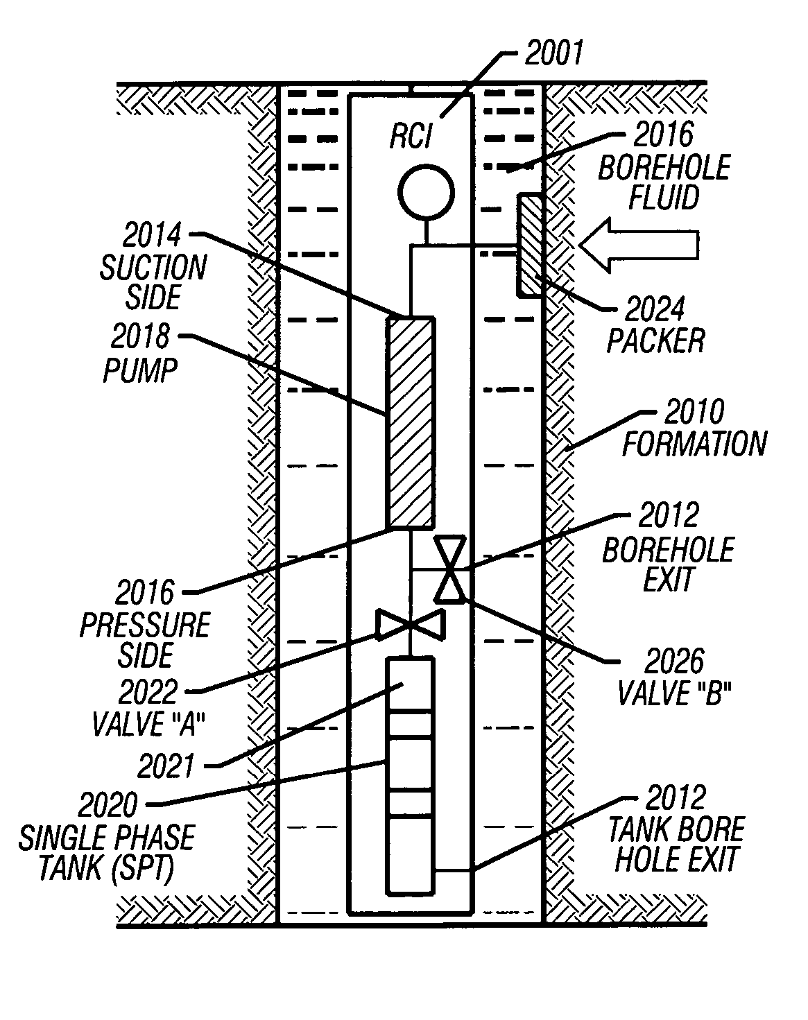
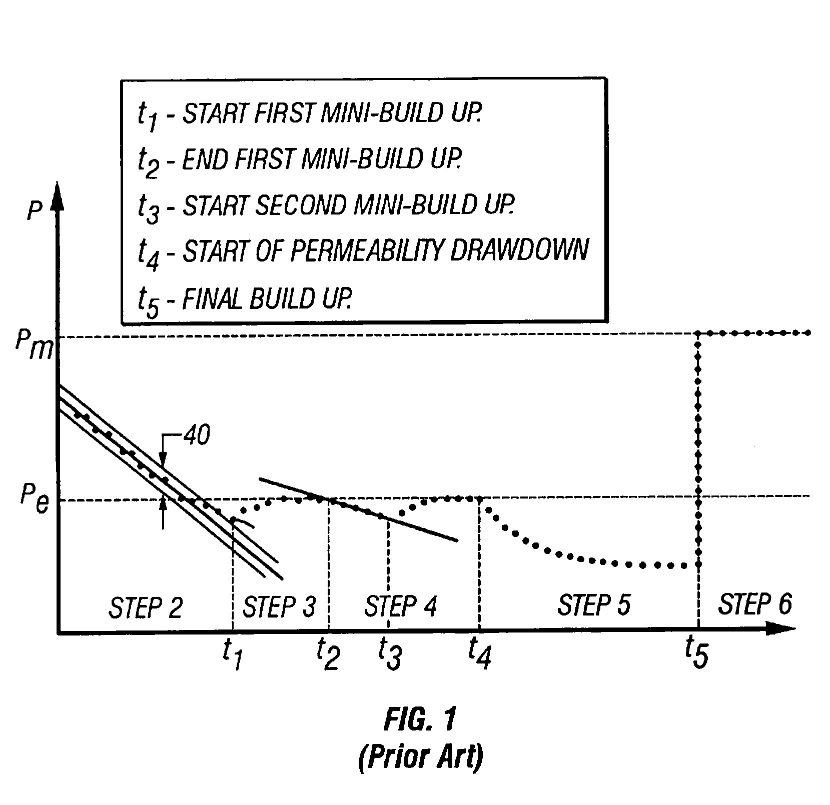
[0015]The present invention plots compressibility of formation fluid versus time during pumping to provide a measure of confidence that formation fluid is substantially free of filtrate contamination before capturing a sample. Determination of permeability versus time also provides an indication as to whether a formation sample is in a single phase state and experiencing laminar flow. The compressibility of filtrate is substantially less than the compressibility of formation fluid containing dissolved gas. The present invention also plots pressure versus flow rate to determine a correlation coefficient for detection of pumping problems such as sanding indicative of the collapse of the reservoir due to pumping too fast. The present invention also matches the pumping rate to formation mobility to ensure a single phase sample in the least amount of time. Pumping too fast can cause the formation fluid upstream of the pump to go into two-phase (gas and liquid) and pumping too slow uses excessive pumping time, which can unnecessarily cost thousands of dollars extra.

Problems solved by technology

Pumping too fast can cause the formation fluid upstream of the pump to go into two-phase (gas and liquid) and pumping too slow uses excessive pumping time, which can unnecessarily cost thousands of dollars extra.

Method used


Image

  • Method and apparatus for pumping quality control through formation rate analysis techniques
  • Method and apparatus for pumping quality control through formation rate analysis techniques
  • Method and apparatus for pumping quality control through formation rate analysis techniques

Examples


Embodiment Construction

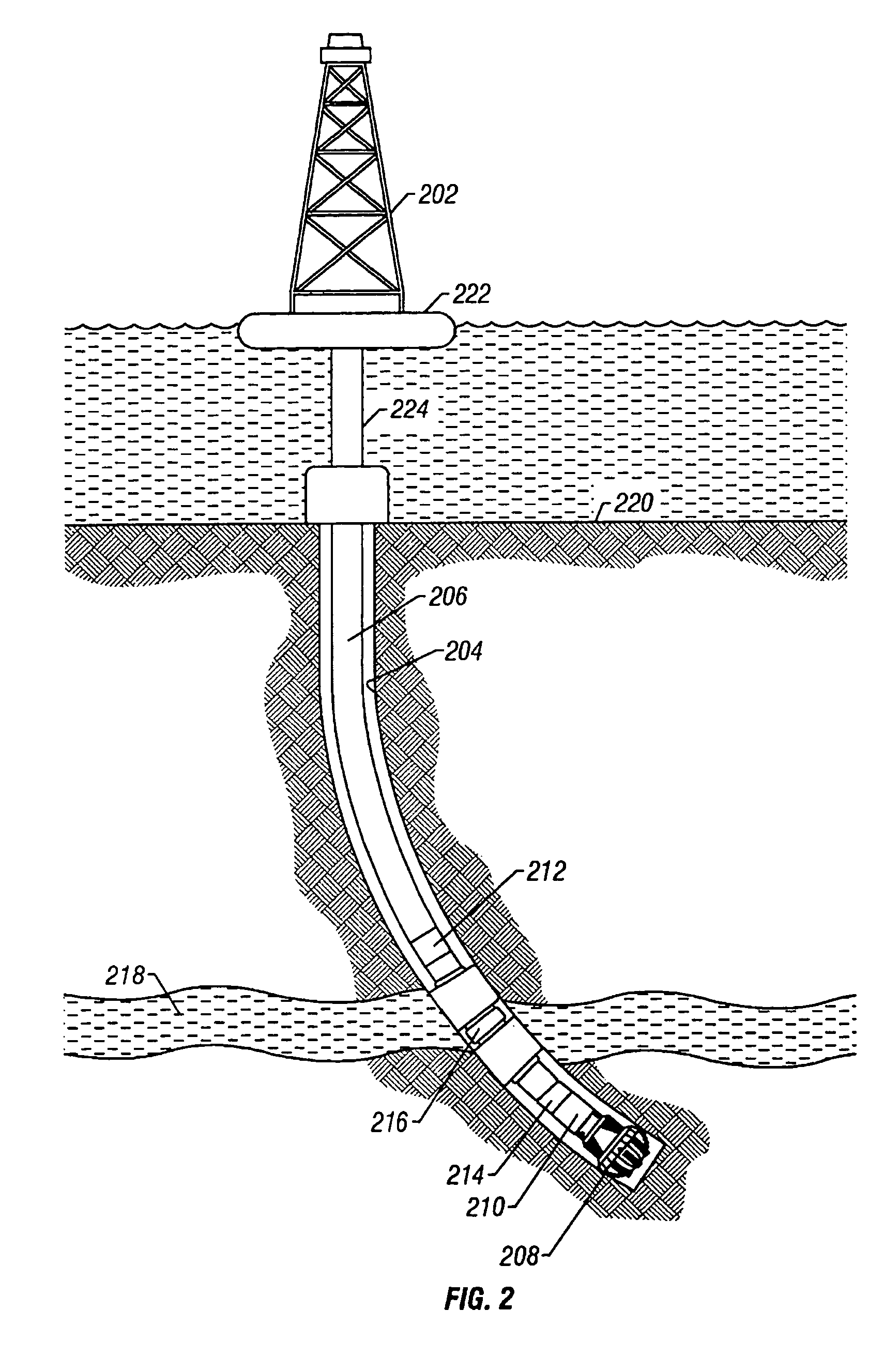
[0037]FIG. 2 is a drilling apparatus according to one embodiment of the present invention. A typical drilling rig 202 with a borehole 204 extending therefrom is illustrated, as is well understood by those of ordinary skill in the art. The drilling rig 202 has a work string 206, which in the embodiment shown is a drill string. The drill string 206 has attached thereto a drill bit 208 for drilling the borehole 204. The present invention is also useful in other types of work strings, and it is useful with a wireline (as shown in FIG. 12), jointed tubing, coiled tubing, or other small diameter work string such as snubbing pipe. The drilling rig 202 is shown positioned on a drilling ship 222 with a riser 224 extending from the drilling ship 222 to the sea floor 220. However, any drilling rig configuration such as a land-based rig may be adapted to implement the present invention.

[0038]If applicable, the drill string 206 can have a downhole drill motor 210. Incorporated in the drill strin...


PUM


Abstract

The present invention provides a method and apparatus for determination of the quality of a formation fluid sample including monitoring permeability and mobililty versus time to determine a filtrate contamination level, single phase state without gas and solids in the formation fluid, as it existed in the formation and the determination of laminar flow from the formation. The present invention also enables determination of an optimal pumping rate to match the ability of a subsurface formation to produce a single phase formation fluid sample in minimum time. The method and apparatus also detect pumping problems such as sanding and loss of seal with borehole.

Description

CROSS REFERENCE TO RELATED APPLICATIONS[0001]This patent application claims priority from U.S. Provisional Patent Application Ser. No. 60 / 453,316 filed on Mar. 10, 2003 and from US. Provisional Patent Application Ser. No. 60 / 464,917 filed on Apr. 23, 2003. This patent application is a continuation in part of U.S. application Ser. No. 09 / 910,209, entitled Closed-Loop Draw down Apparatus and Method for In-Situ Analysis of Formation Fluids, by V. Krueger et al. filed on Jul. 20, 2001, now U.S. Pat. No. 6,609,568 issue on Aug. 26, 2003 published on Aug. 22, 2002 which is incorporated herein by reference in its entirety, which along with the current application is commonly owned by Baker Hughes, Incorporated.BACKGROUND OF THE INVENTION[0002]1. Field of the Invention[0003]The present invention relates generally to the field of quality control for formation fluid sampling and in particular to the determination of permeability and mobility versus time to provide an indication as to whether ...

Claims


Application Information

Patent Timeline
Patent Type & Authority Patents(United States)
IPC IPC(8): E21B49/10E21B49/00E21B49/08
CPCE21B49/008E21B49/081E21B49/10
Inventor SHAMMAI, MICHAELLEE, JAEDONG
Owner BAKER HUGHES INC
Why Eureka
Try Eureka