Eccentric oscillating gear mechanism and industrial robot joint construction using the same

a gear mechanism and eccentric technology, applied in the direction of gearing, toothed gearings, program-controlled manipulators, etc., can solve the problems of deteriorating working efficiency and safety, damaged cables and other members, etc., and achieve the effect of facilitating the assembling work of the joint construction of industrial robots

Active Publication Date: 2009-05-14
NABLESCO CORP
View PDF9 Cites 15 Cited by
  • Summary
  • Abstract
  • Description
  • Claims
  • Application Information

AI Technical Summary

Benefits of technology

[0012]The invention has been made in view of the problems, and an object thereof is to provide an eccentric oscillating gear mechanism which can support rotatably a cylindrical tube body so as to eliminate a possibility of cables and other members which pass through an interior of the cylindrical tube body being damaged and obviate the necessity of the cylindrical tube body being built in an industrial robot.
[0017]In addition, according to the second aspect of the invention, since the outer circumferential portion of at least one end portion of the cylindrical tube body constitutes the engagement portion with the seal member, a sealed construction can easily be constructed via the mating member like a fixing portion of a robot and the seal member.
[0018]Furthermore, according to the third aspect of the invention, since the internal gear is fixed to the fixing portion of the industrial robot, and the end portion of the cylindrical tube body is inserted into the central hole provided in the fixing portion via the seal member, the assembling work of the joint construction of the industrial robot can be facilitated.

Problems solved by technology

Due to the rubbing contact of the cylindrical tube body 330 with the cables and other members 380 for a long period of time, there is caused a problem that the cables and other members are damaged.
However, to place the cylindrical tube body 330 into the fixing portion 350 of the robot in the way described above, the robot has to be lifted to be suspended by a crane or the like so that the cylindrical tube body is inserted into the fixing portion from therebelow and is then fixed thereto with bolts or the like, resulting in deteriorated working efficiency and safety.

Method used


Image

  • Eccentric oscillating gear mechanism and industrial robot joint construction using the same
  • Eccentric oscillating gear mechanism and industrial robot joint construction using the same
  • Eccentric oscillating gear mechanism and industrial robot joint construction using the same

Examples


embodiment

[0026]Hereinafter, an embodiment of the invention will be described based on drawings.

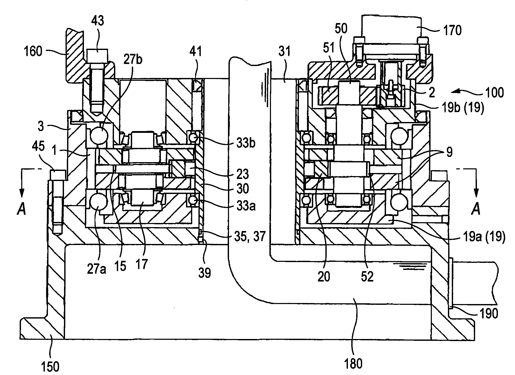
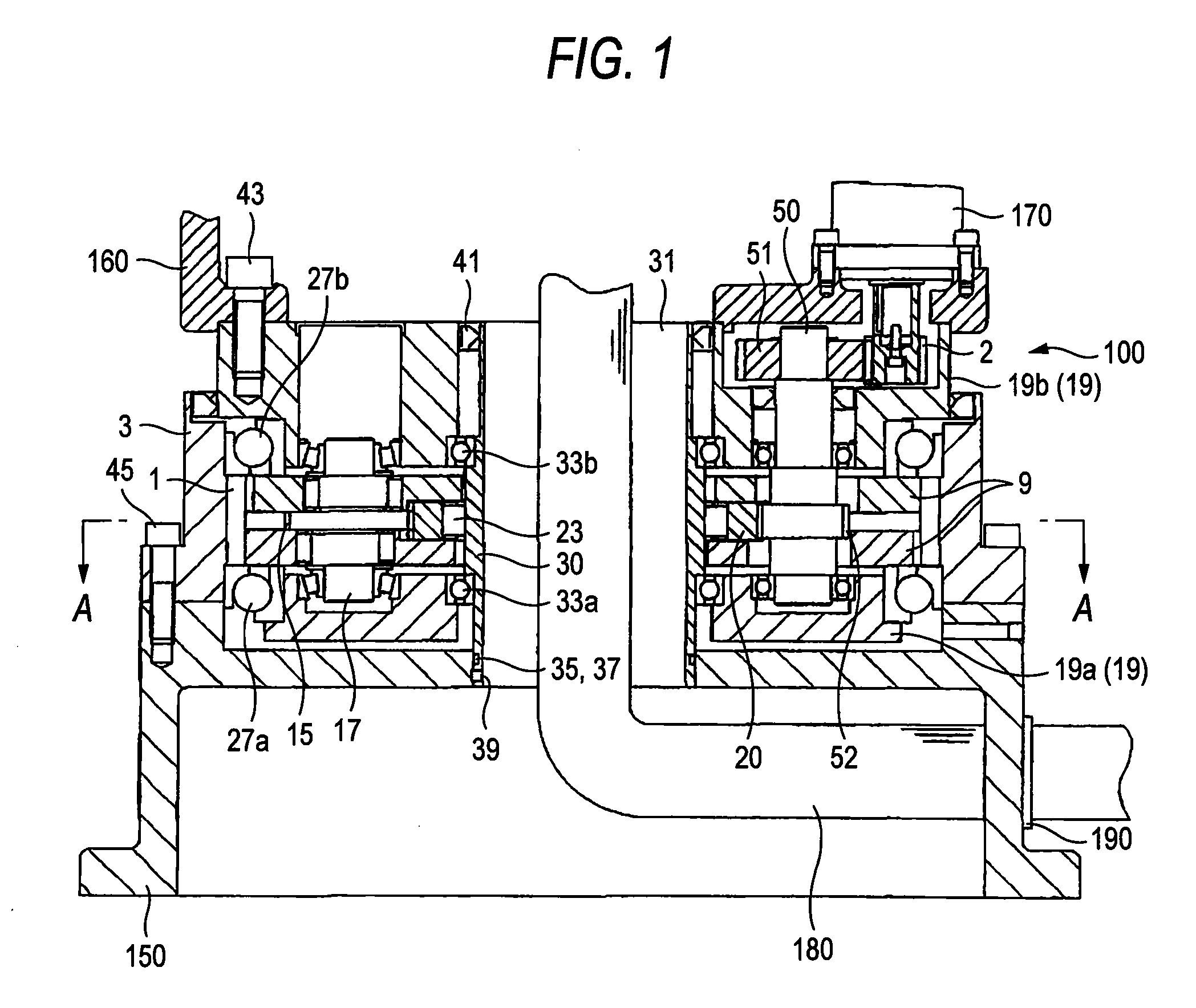
[0027]FIG. 1 is a drawing showing an example in which an eccentric oscillating gear mechanism of the invention is used in a turning part of an industrial robot, and FIG. 2 is a sectional view taken along the line A-A of the eccentric oscillating gear mechanism shown in FIG. 1. FIG. 3 is a sectional view taken along the line B-B in FIG. 2.

[0028]An eccentric oscillating gear mechanism 100 is made up of an internal gear 3 having internal teeth made up of a large number of pins, two external gears 9 which mesh with the internal gear 3, three crankshafts 17 for moving the external gears 9 eccentrically, and a carrier 19 which is made up of a pair of end plate portions 19a, 19b and a plurality of pillar portions 21 which connect together the pair of endplate portions and which supports rotatably the crankshafts 17, and the internal gear 3 and the carrier 19 are made to rotate relatively by means of a pai...


PUM


Abstract

There is provided an eccentric oscillating gear mechanism including an internal gear, an external gear meshing with the internal gear, a crankshaft for moving the external gear eccentrically, and a carrier for supporting rotatably the crankshaft, the internal gear and the carrier being made to rotate relatively, wherein a cylindrical tube body, which penetrates the eccentric oscillating gear mechanism in an axial direction, is supported rotatably on the carrier.

Description

BACKGROUND OF THE INVENTION[0001]1. Field of the Invention[0002]The present invention relates to an eccentric oscillating gear mechanism for use in a joint portion of an industrial robot.[0003]2. Related Art[0004]There have conventionally been known eccentric oscillating gear mechanisms such as those used in joint portions of industrial robots (hereinafter, also referred to simply as a “robot” from time to time) which are described in JP-A-9-57678 and JP-A-2001-323972 below.[0005]Eccentric oscillating gear mechanisms described in JP-A-9-57678 and JP-A-2001-323972 are an eccentric oscillating gear mechanism which includes an internal gear, an external gear which meshes with the internal gear, a crankshaft which moves the external gear eccentrically, and a carrier which supports the crankshaft rotatably. The internal gear and the carrier are made to rotate relatively. The eccentric oscillating gear mechanism includes a hollow hole which is made axially about an axis thereof, and a cyl...

Claims


Application Information

Patent Timeline
Patent Type & Authority Applications(United States)
IPC IPC(8): F16H23/00
CPCF16H1/32B25J9/102
Inventor MIYOSHI, HIROYUKI
Owner NABLESCO CORP
Why Eureka
Try Eureka