
Membrane computing

Inactive Publication Date: 2009-05-14
TECHNION RES & DEV FOUND LTD
View PDF5 Cites 10 Cited by
  • Summary
  • Abstract
  • Description
  • Claims
  • Application Information

AI Technical Summary

Benefits of technology

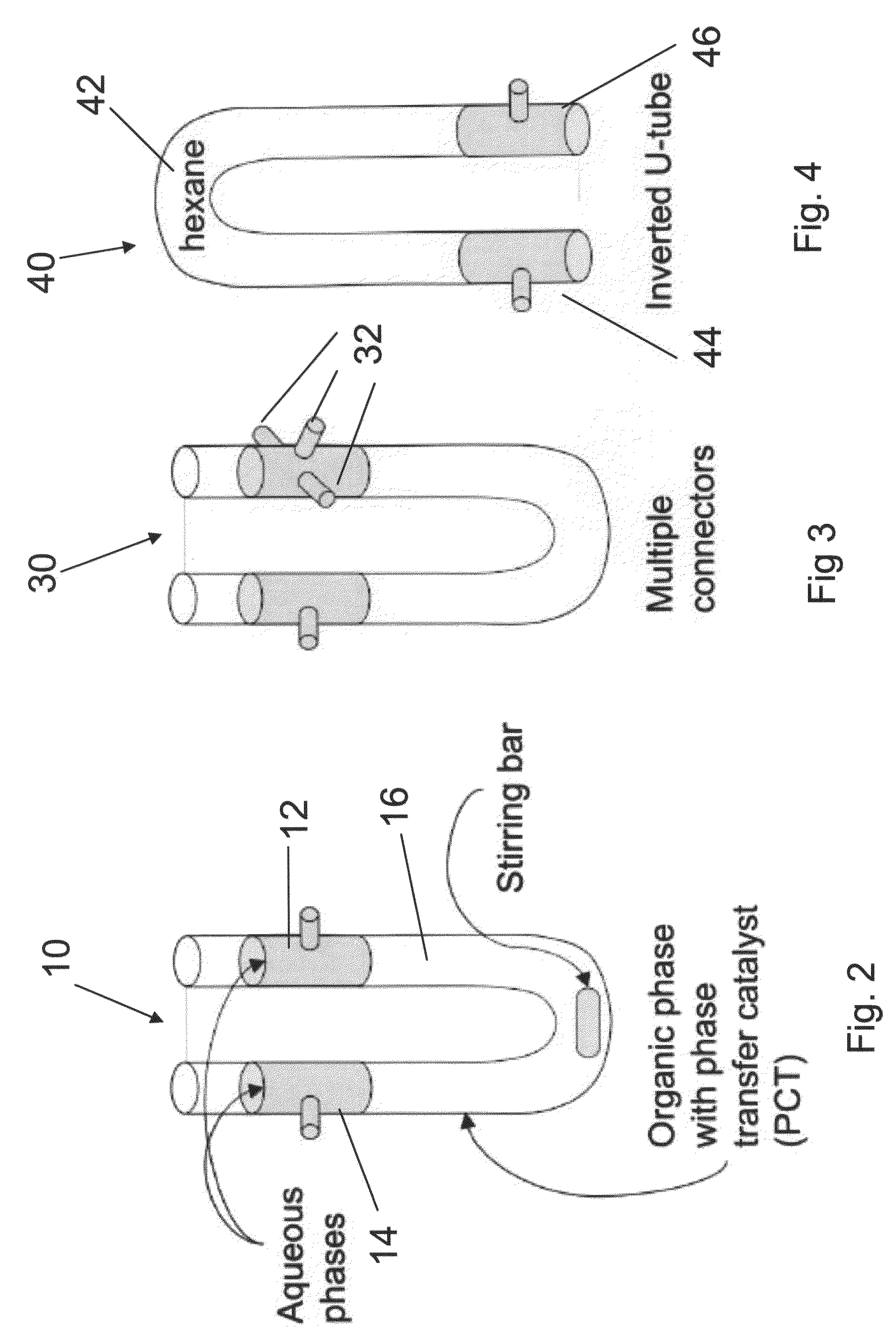
[0022]An embodiment may include branches for connecting each liquid phase to that of a neighboring component, thereby to allow construction of a component array.

Problems solved by technology

However, to date, the P systems are all theoretical models that have never been reduced to practice.

Method used


Image

  • Membrane computing
  • Membrane computing
  • Membrane computing

Examples


Embodiment Construction

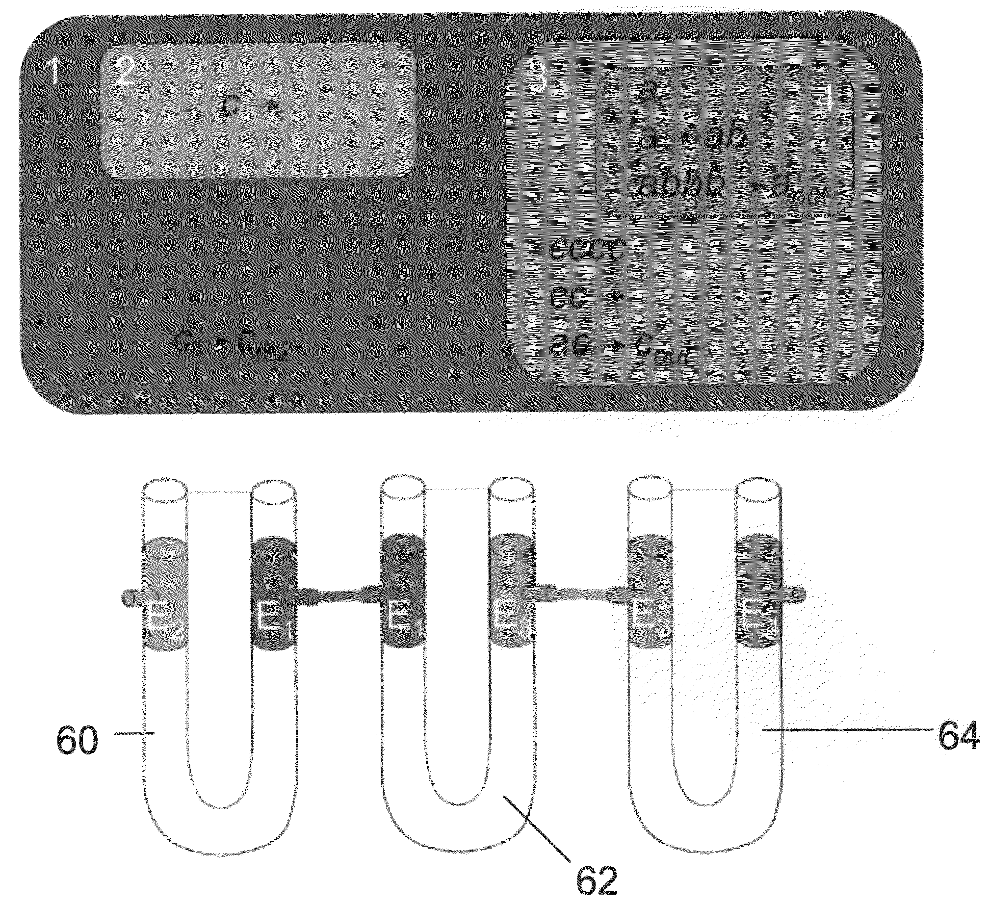
[0050]The present invention, in some embodiments thereof, relates to an apparatus and method for carrying out membrane computing in practice and, more particularly, but not exclusively, to an apparatus and method of providing a practical membrane having the properties required by membrane computing to separate between two phases while allowing controlled functional interaction between them.

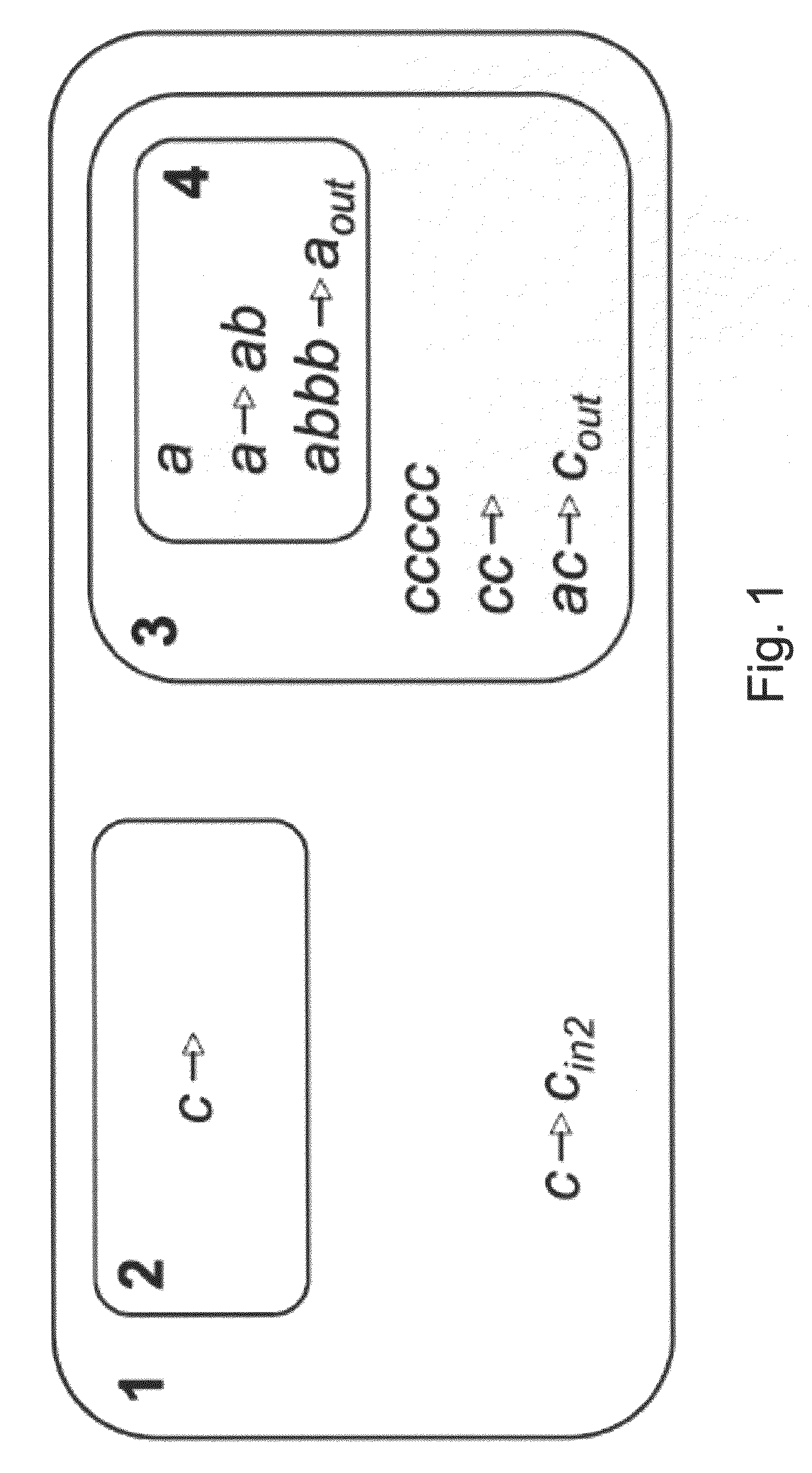
[0051]For purposes of better understanding some embodiments of the present invention, reference is first made to the theoretical P model as illustrated in FIG. 1. It is noted that since this model has never been reduced to practice to date it is not believed to be prior art in the patent sense even though it has been previously published.

[0052]FIG. 1 illustrates an example of a P system, currently only known from theory, and represented graphically with four membranes labeled with consecutive integers. Membrane 1 is the skin membrane, and contains membranes two and three as well as a rule. The par...


PUM

PropertyMeasurementUnit
electrochemical activityaaaaaaaaaa
pHaaaaaaaaaa
fluorescenceaaaaaaaaaa

Abstract

A method of implementation of a P-system in membrane computing comprising: placing three mutually immiscible liquids into a container, such that a first of said liquids provides a barrier between the second and third liquids; providing an initial substrate to at least one of said second and third liquids; and applying a transport rule for said first liquid to allow transport of substrate between said second and said third liquid.

Description

RELATED APPLICATION / S[0001]This application claims the benefit of U.S. Provisional Patent Application No. 60 / 984,834 filed Nov. 2, 2007.[0002]The contents of the above document is incorporated by reference as if fully set forth herein.FIELD AND BACKGROUND OF THE INVENTION[0003]The present invention, in some embodiments thereof, relates to an apparatus and method for carrying out membrane computing in practice and, more particularly, but not exclusively, to an apparatus and method of providing a practical membrane having the properties required by membrane computing to separate between two phases while allowing controlled functional interaction between them.[0004]Membrane computing (MC) is an area of computer science aiming to abstract computing ideas and models from the structure and the functioning of living cells, as well as from the way the cells are organized in tissues or higher order structures. In short, MC deals with distributed and parallel computing models, processing mult...

Claims


Application Information

Patent Timeline
Patent Type & Authority Applications(United States)
IPC IPC(8): C40B30/00B01J19/00C12M1/00G01N21/64G01N21/76C12Q1/00
CPCG06N99/007B82Y10/00
Inventor KEINAN, EHUD
Owner TECHNION RES & DEV FOUND LTD
Learn More