Passive valve with stop pad

Active Publication Date: 2009-05-21
FAURECIA EMISSIONS CONTROL TECH GERMANY
View PDF11 Cites 12 Cited by
  • Summary
  • Abstract
  • Description
  • Claims
  • Application Information

AI Technical Summary

Benefits of technology

[0011]In one example, the stop comprises a ramped surface that begins upstream of the vane. An exhaust component has a wall with an external surface and an internal surface that defines the exhaust gas flow path. The ramped surface extends from the internal surface of the wall toward the vane.

Problems solved by technology

Although effective, these components are often relatively large in size and provide limited nose attenuation.
Increasing muffler volume is disadvantageous from a cost, material, and packaging space perspective.
Increasing backpressure can adversely affect engine power.
With the use of the spring, it is difficult to return the vane to

Method used


Image

  • Passive valve with stop pad
  • Passive valve with stop pad
  • Passive valve with stop pad

Examples


Embodiment Construction

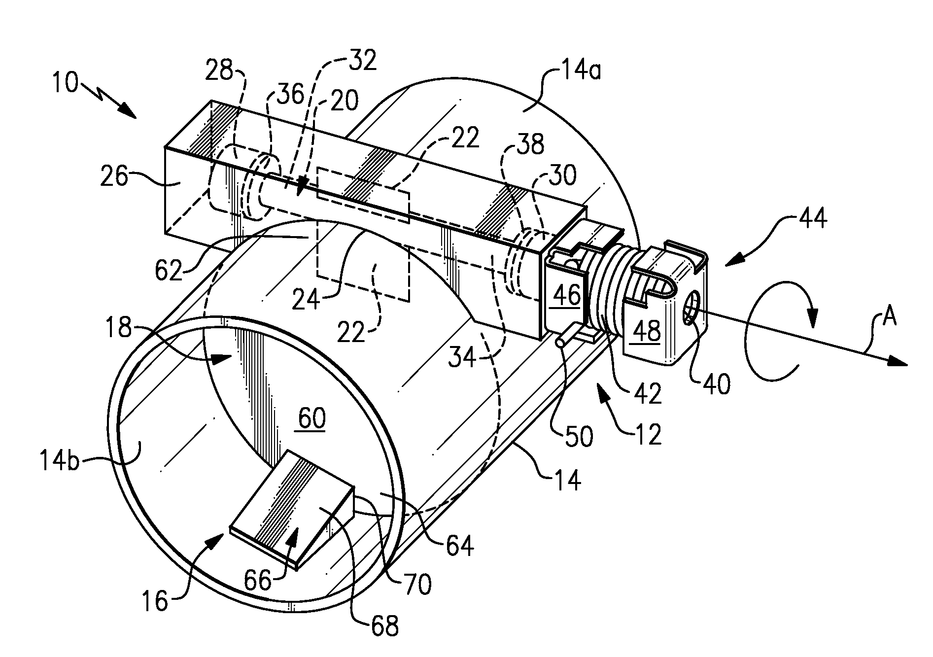
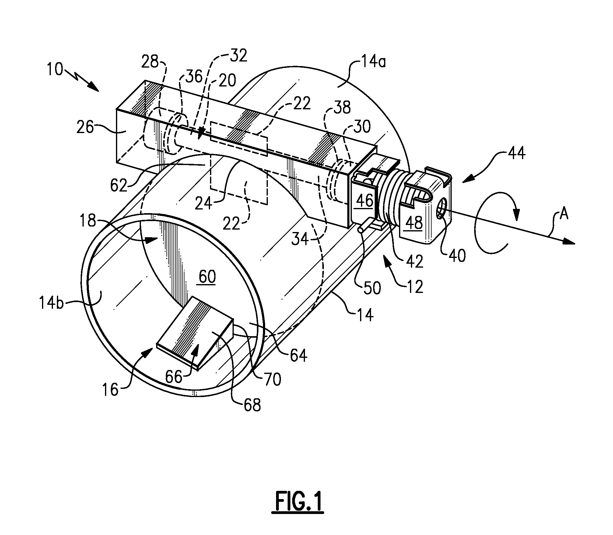
[0024]As shown in FIG. 1, an exhaust component, such as an exhaust tube or pipe 10 includes an exhaust throttling valve, referred to as a passive valve assembly 12. The passive valve assembly 12 is movable between an open position where there is minimal blockage of an exhaust gas flow path 16 and a closed position where a substantial portion of the exhaust gas flow path 16 is blocked. The passive valve assembly 12 is resiliently biased toward the closed position and is moved toward the open position when exhaust gas flow generates a pressure sufficient enough to overcome the biasing force.

[0025]In the example shown, the exhaust pipe 10 comprises a single pipe body 14 that defines the exhaust gas flow path 16. In one example, the pipe body 14 includes a curved outer surface 14a and a curved inner surface 14b that defines the exhaust gas flow path 16. In one example, the pipe body 14 has a circular cross-section.

[0026]The passive valve assembly 12 includes a valve body or vane 18 that...


PUM


Abstract

A passive valve assembly for an exhaust component includes a vane that is positioned within an exhaust gas flow path. The vane is pivoted from a closed position to an open position in response to exhaust gas flow overcoming a biasing force. A stop is positioned within the exhaust component and cooperates with the vane to define a closed position for the vane.

Description

RELATED APPLICATIONS[0001]This application claims priority to provisional application No. 60 / 989,508 filed on Nov. 21, 2007.TECHNICAL FIELD[0002]The subject invention relates to a passive valve in a vehicle exhaust system, and more particularly to a passive valve with a stop pad that facilitates noise reduction while also improving valve performance and durability.BACKGROUND OF THE INVENTION[0003]Exhaust systems are widely known and used with combustion engines. Typically, an exhaust system includes exhaust tubes that convey hot exhaust gases from the engine to other exhaust system components, such as mufflers, resonators, etc. Mufflers and resonators include acoustic chambers that cancel out sound waves carried by the exhaust gases. Although effective, these components are often relatively large in size and provide limited nose attenuation.[0004]Attempts have been made to improve low frequency noise attenuation by either increasing muffler volume or increasing backpressure. Increas...

Claims


Application Information

Patent Timeline
IPC IPC(8): F01N7/00F01N13/02F01N13/08
CPCF01N13/08F01N2240/36F01N2260/06F01N1/02F02D9/1025F02D9/1065F02D9/04
Inventor ABRAM, KWINKALYANASAMY, GOVINDARAJWILLATS, ROBIN
Owner FAURECIA EMISSIONS CONTROL TECH GERMANY
Why Eureka
Try Eureka