Docking and Drilling Stations for Running Self-Standing Risers and Conducting Drilling, Production and Storage Operations

a technology for drilling stations and risers, applied in the field of offshore facilities, can solve the problems of significant delays in many drilling projects, shortfall of offshore drilling units called mobile offshore drilling units, and dramatic increase in the cost of obtaining either a new or existing modu for exploration and production operations

Inactive Publication Date: 2009-05-21
MILLHEIM KEITH K
View PDF4 Cites 18 Cited by
  • Summary
  • Abstract
  • Description
  • Claims
  • Application Information

AI Technical Summary

Benefits of technology

[0009]A sea vessel exploration and production system is provided, wherein the system includes a drilling station formed from at least one section of a first sea vessel hull; and a docking station, which is also formed from at least one section of a second sea vessel hull. A mooring system suitable for connecting the drilling station to the docking station is also provided. Means for anchoring the vessels to the seafloor, and for attaching them to turret buoys, are also considered. Various exploration and production packages, as well as equipment required to deploy and control a self-standing riser system in either deep or shallow waters, are also described.

Problems solved by technology

There is, however, a serious shortfall of offshore drilling units called Mobile Offshore Drilling Units, or MODUs.
The relative unavailability of MODUs has resulted in significant delays in many drilling projects.
Consequently, the cost of obtaining either a new or existing MODU for an exploration and production operation has dramatically increased over the past decade.
However, due to the lack of floating production facilities and the high cost of MODUs, early testing is seldom accomplished, which often results in unnecessary delays and inaccurate predictions of economic assessments, project development schedules, etc.
Moreover, procurement of offshore production and storage facilities required to operate offshore projects in a timely manner can be quite difficult.
However, as those of skill in the art have learned in the field, buoy-based systems utilizing general purpose vessels for riser and buoyancy chamber deployment are deficient in that large-scale operations (e.g., deployment in very deep or turbulent waters, or projects involving multiple combinations of riser strings and buoyancy chambers, etc.) are very difficult to control, and thus installation, operation and maintenance of the resulting system is significantly impaired.

Method used


Image

  • Docking and Drilling Stations for Running Self-Standing Risers and Conducting Drilling, Production and Storage Operations
  • Docking and Drilling Stations for Running Self-Standing Risers and Conducting Drilling, Production and Storage Operations
  • Docking and Drilling Stations for Running Self-Standing Risers and Conducting Drilling, Production and Storage Operations

Examples


Embodiment Construction

[0019]The description that follows includes exemplary systems, methods, and techniques that embody various aspects of the presently inventive subject matter. However, it will be readily understood by those of skill in the art that the disclosed embodiments may be practiced without one or more of these specific details. In other instances, well-known manufacturing equipment, protocols, structures and techniques have not been shown in detail in order to avoid obfuscation in the description.

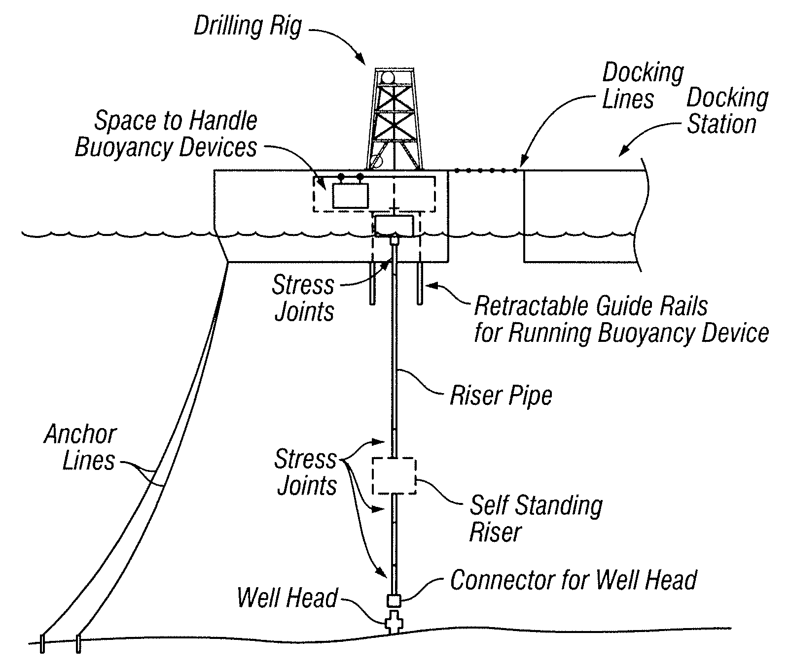
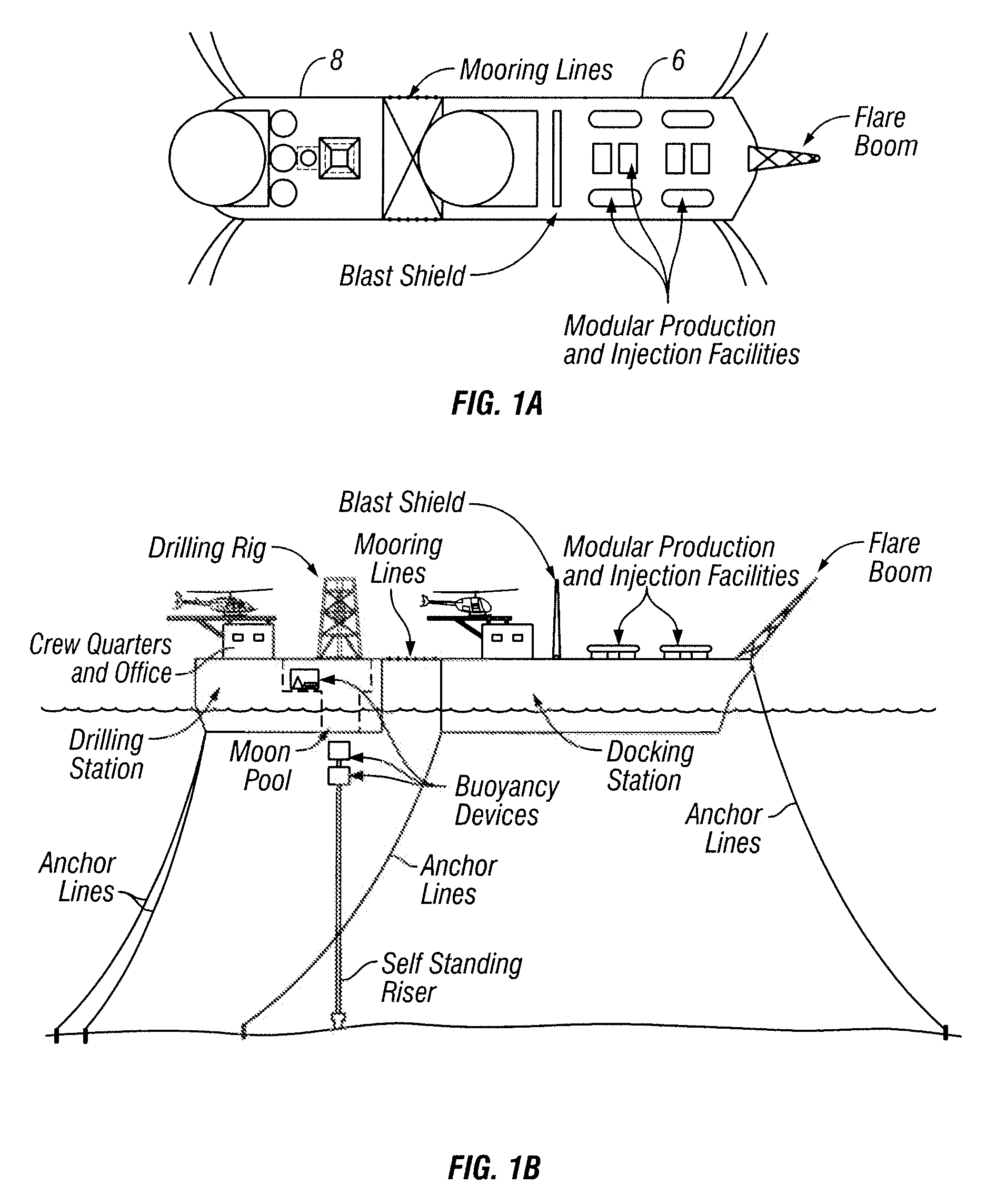
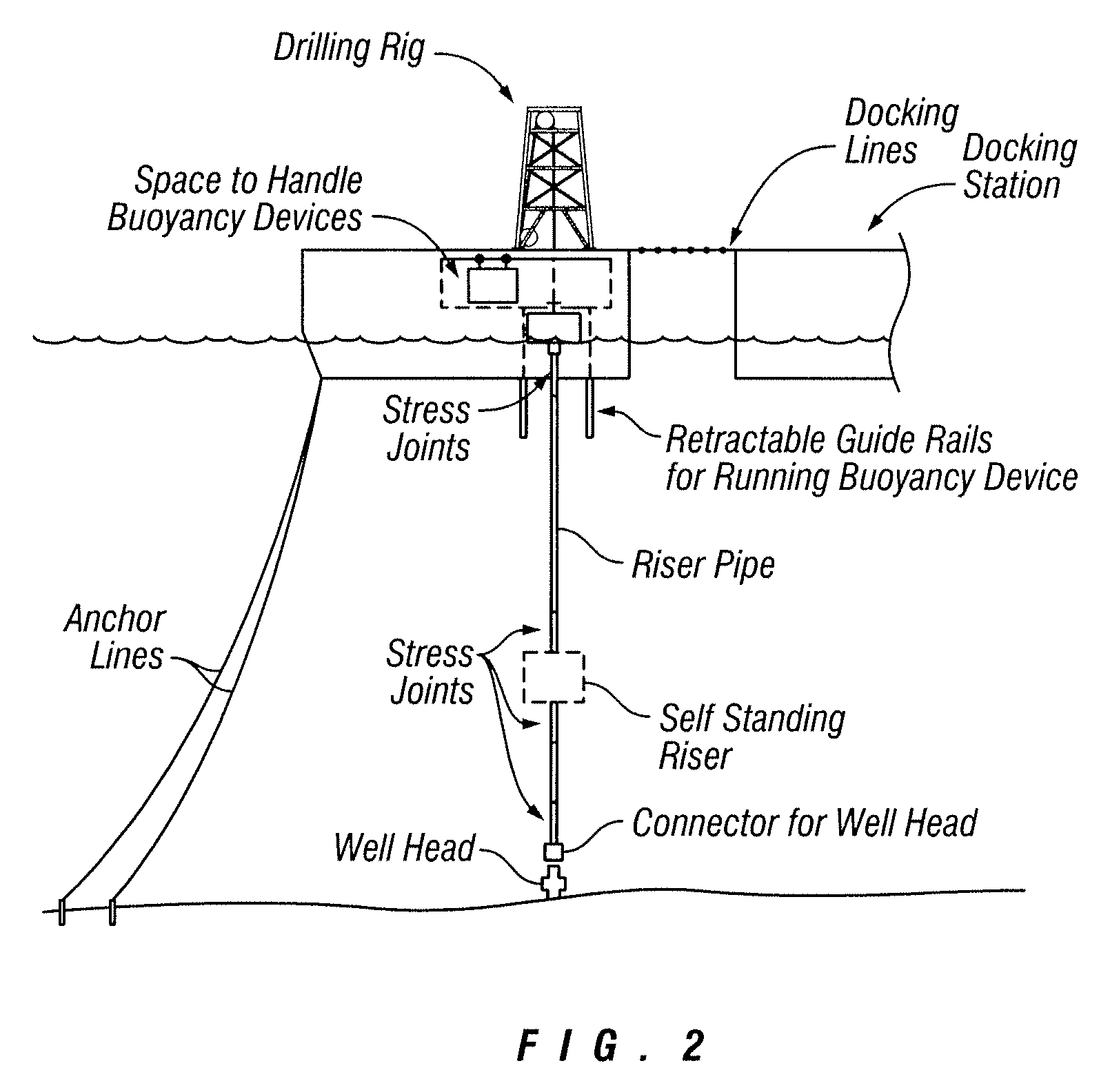
[0020]Referring now to the example embodiment illustrated in FIG. 1A, an overhead view of a docking station 6 and a drilling station 8 are depicted as being moored together in an end-to-end manner. The embodiment of the drilling station shown in FIG. 1B comprises crew quarters and an operations office; a drilling rig; a void space designed for housing and deploying various buoyancy devices; a helipad; a moon pool; a plurality of anchor lines used to anchor the system to an associated seabed; and moo...


PUM


Abstract

A sea vessel exploration and production system is provided, wherein the system includes a drilling station formed from at least one section of a first sea vessel hull; and a docking station, which is also formed from at least one section of a second sea vessel hull. A mooring system suitable for connecting the drilling station to the docking station is also provided. Means for anchoring the vessels to the seafloor, and for attaching them to turret buoys, are also considered. Various exploration and production packages, as well as equipment required to deploy and control a self-standing riser system in either deep or shallow waters, are also described.

Description

CROSS REFERENCE TO RELATED APPLICATIONS[0001]The present application claims the benefit of prior U.S. Provisional Application No. 61 / 003,657, filed Nov. 19, 2007.FIELD OF THE INVENTION[0002]The present invention relates generally to offshore facilities used in connection with the exploration and production of oil and gas, and in a particular though non-limiting embodiment, to a docking and drilling vessel system suitable for deploying self-standing risers and conducting oil and gas drilling, production and storage operations.BACKGROUND OF THE INVENTION[0003]Offshore drilling is quickly becoming the prevalent method of exploring and producing oil and gas, especially in Western countries where land operations are frequently inhibited by environmental concerns. There is, however, a serious shortfall of offshore drilling units called Mobile Offshore Drilling Units, or MODUs. The relative unavailability of MODUs has resulted in significant delays in many drilling projects. Consequently, ...

Claims


Application Information

Patent Timeline
Patent Type & Authority Applications(United States)
IPC IPC(8): B63B35/44
CPCB63B21/508B63B35/44B63B2035/448B63B35/4413B63B2021/003B63B21/507B63B21/00E21B43/013
Inventor MILLHEIM, KEITH K.
Owner MILLHEIM KEITH K
Why Eureka
Try Eureka