Liquid ejection device and ejection method

a liquid ejection device and liquid technology, applied in the direction of other medical devices, powder delivery, disinfection, etc., can solve the problems of difficult to retain respective substances in a mixture, hardly constructed to precisely control an amount of ejection, and difficult to precisely control the amount of ejection. , to achieve the effect of easy chang

Inactive Publication Date: 2009-05-21
CANON KK
View PDF12 Cites 88 Cited by
  • Summary
  • Abstract
  • Description
  • Claims
  • Application Information

AI Technical Summary

Benefits of technology

[0008]In view of the above-mentioned problems, an object of the present invention is to provide a liquid ejection device, with which an ejection amount or...

Problems solved by technology

Among such various conceivable combinations, some of them may be difficult to retain respective substances in a mixture, though they are expected to be ejected or atomized in a mixed state.
In other words, each substance may lose its original beneficial effects as a result of reaction with others in mixt...

Method used


Image

  • Liquid ejection device and ejection method
  • Liquid ejection device and ejection method
  • Liquid ejection device and ejection method

Examples


example 1

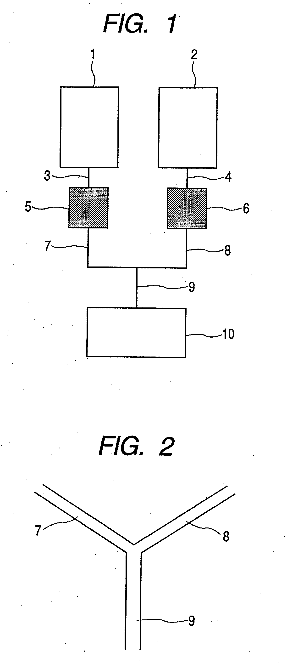
[0062]Storing parts 1 and 2 were filled with a solution A and a solution B described below, respectively. In addition, piezoelectric pumps were used in liquid-feeding parts 5 and 6, respectively. The pump is specified that 5 μl of liquid can be fed when the pump is actuated at 50 Hz for one second. For the actual actuation of the pumps, the frequencies of the pumps for solutions A and B were respectively set to 40 and 10 Hz and simultaneously actuated for one second to feed 4 μl of the solution A and 1 μl of the solution B, respectively.

[0063]Solution A: an aqueous solution of 4 mg / ml insulin

[0064]Solution B: an aqueous solution of 20 mg / ml lauroyl sarcosine

[0065]A ejection part 10 having 400 nozzles of 3 μm in nozzle diameter was used. The mixture liquid was atomized for one second and then re-atomized with 4 seconds intervals, thereby carrying out atomization 50 times in total. For repeating atomization, the liquid feeding and liquid supply were appropriately carried out. Furt...

example 2

[0073]In Example 1, the substance in the solution B was changed to arginine, the set value of the pump was changed to 40 Hz, and the amount of a liquid to be fed was changed to 4 μl. As the both liquid-feeding parts had the same drive frequency, the liquid-feeding parts were controlled so that their actuation timings were staggered. In addition, the same evaluation by atomizing as that of Example 1 was carried out after two-month storage of the solutions A and B at 30° C. As a result, all of 50 atomization trials were succeeded. In addition, the ratio of 0.08 was obtained with respect to the concentration ratio of the liquid, which was mixed and fed.

examples 3 to 5

[0074]In Example 2, the contents of the liquid was changed to those represented in Table 1 and then evaluated in the same way as that of Example 2. The results obtained are shown in Table 1. That is, it was found that the mixture ratio could be controlled precisely.


PUM


Abstract

A liquid ejection device, includes: a plurality of storing parts for storing liquids; a plurality of liquid-feeding parts connected to the respective storing parts; a ejection part for ejecting a liquid; a plurality of flow paths connected to the plurality of liquid-feeding parts, respectively; and a connection part for joining the plurality of flow paths and connecting them as a single flow path to the ejection part. The plurality of liquid-feeding parts are actuated to mix the liquids from the plurality of storing parts in the single flow path joined at the connection part and feed a mixture of the liquids to the ejection part to eject the mixture from the ejection part. According to the ejection device of the present invention, the ejection amount or the mixing ratio can be easily changed in a comparatively precise manner.

Description

TECHNICAL FIELD[0001]The present invention relates to an ejection device and an ejection method for ejecting a liquid. More specifically, the present invention is applicable to an ejection mechanism to be utilized in an equipment for generating predetermined airflow under atmospheric pressure, including liquid-atomizing medical equipment such as inhalers and feeders for nasal drops, or air conditioners, air cleaners, ventilating facilities, and air-inlet facilities. As described above, the present invention relates to a liquid ejection device and a liquid ejection method, which can be extensively applicable depending on usage forms thereof.BACKGROUND ART[0002]Various kinds of equipments for generating a predetermined air flow under atmospheric pressure have been known in the art, extending from industrially applicable equipment to house-hold equipment. In addition, variations include a wide variety of equipment such as those for air supply, air suction, air replacement, air purifica...

Claims


Application Information

Patent Timeline
IPC IPC(8): A61M11/00
CPCA61K9/0073A61L9/03A61L9/14A61L2209/134A61M15/0065A61M15/0085A61M2205/588A61M2205/8206A61M11/042A61M15/0003A61M15/025
Inventor SUGITA, MASARUWADA, HIROYUKI
Owner CANON KK
Why Eureka
Try Eureka