As a result, portions of the side frames 2 and portions of the upper rail members A which are strongly abutted against each other are deformed and / or damaged.
Moreover, in a case where the height adjusting device is applied to a slide-type automobile seat with a
position sensor system, in which position sensors, electrical wirings thereof and / or the like (any automotive electronic parts and / or the like) are arranged on upper surfaces of upper rail members of a slide rail mechanism or arranged in the vicinity of the upper rail members, when the occupant on the seat operates the operating knob in such a manner that the seat is excessively lowered, or any excessive load is applied to the seat in a condition where the seat has been in a lowermost position, side frames of the seat are abutted against the position sensors, the electrical wirings and / or the like, to thereby cause them to be damaged.
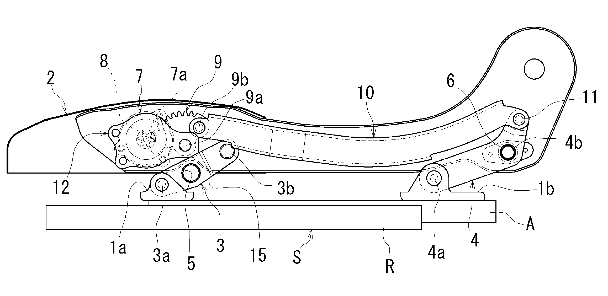
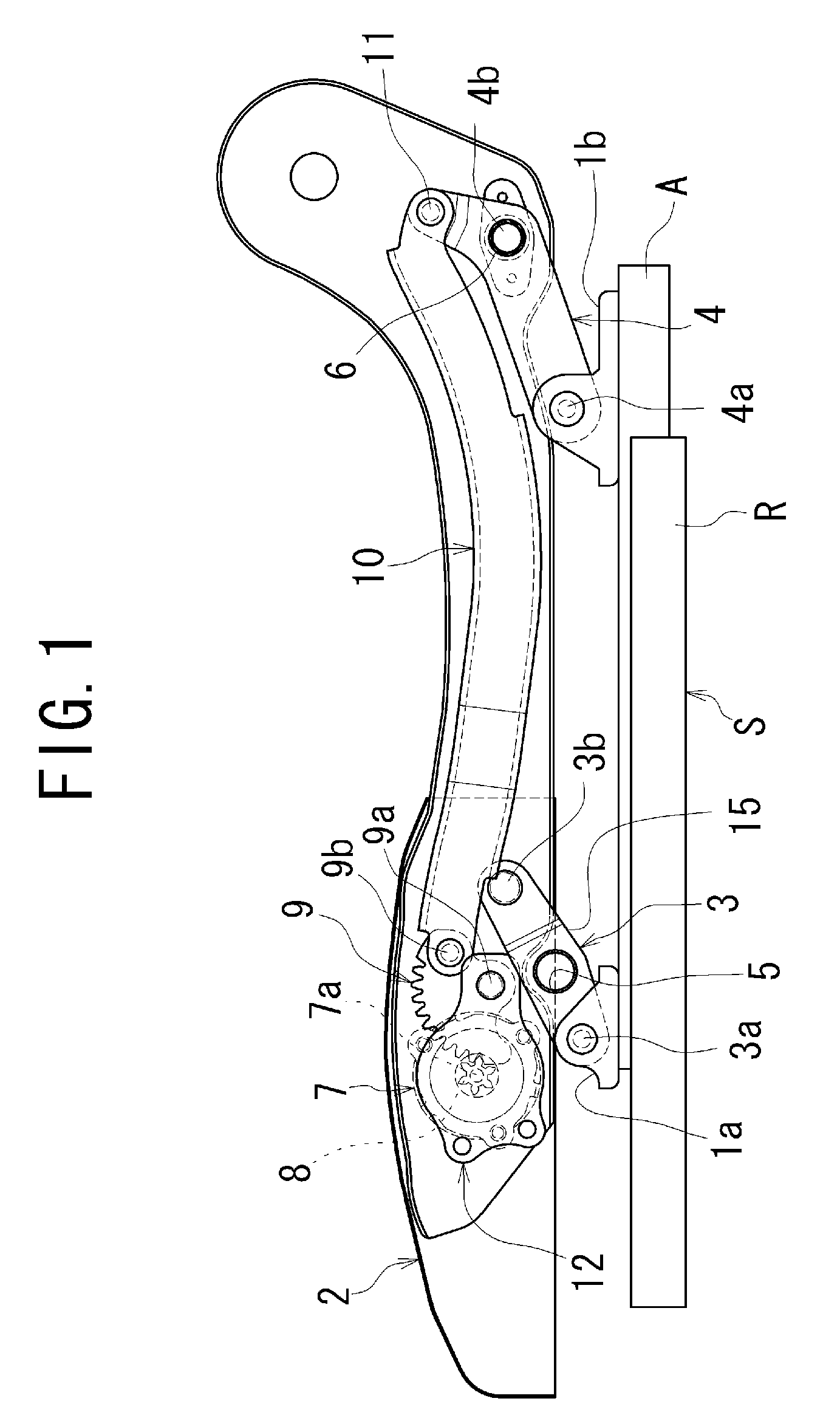
Moreover, the height adjusting device comprises several parts including the forward and rearward linkage members 3, 4 which are supported to the side frames 2 of the seat
cushion, and the operating knob 7, the
pinion gear 8, the sector gear 9, and the rod 10 which are supported to the one of the side frames 2, so that the structures of the side frame and / or arrangement of the parts around the side frame is likely to become complicated.
Particularly, a considerable load, such as a weight load of the seat itself and / or a weight load of the occupant on the seat, is applied to the support pins 3b, 4b supporting the forward and rearward linkage members 3, 4, and the support pin 9a of the sector gear 9, so that positional relationships among them with respect to the side frame are hard to be determined, and the structure of the height adjusting device is likely to become complicated.
Moreover, in the height adjusting device for the automobile seat, if the rigidity of the linkage base frame 15 is poor and a considerable load is applied to the linkage base frame 15, the forward and rearward linkage members 3, 4 and parts around them are made to flex, so that the seat is hard to be stably supported, and / or it is hard to carry out the adjusting of the height of the seat.
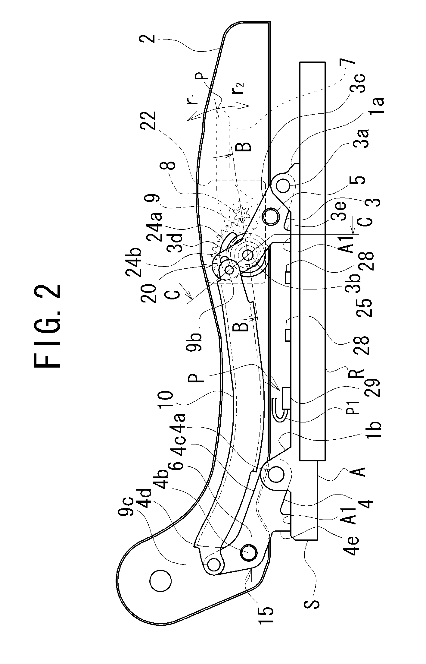
However, the forward linkage member 3 which is arranged in the vicinity of the parts including the operating knob 7, the
pinion gear 8, the sector gear 9 and the rod 10 is required not to interfere with their operations, so that the arrangement and shape of the forward linkage member 3 is considerably limited and it is not easy to ensure the good rigidity of the linkage base frame 15.
When the height of the seat is to be adjusted, lifting of the linkage base frame 15 must be performed against the total weight load by only operating the operating knob, so that a considerable force is required in order to operate the operating knob and, therefore, it is hard to operate the operating knob.
Therefore, there is a problem that the height adjusting device becomes large-sized and a lowermost position of the seat is inevitably set so as to become high.
Therefore, in order that they can be effectively and smoothly operated, the structure of the height adjusting device is likely to become complicated.

