Electrical machine with magnetic brake directly on the rotor

a technology of electric machines and rotors, which is applied in the direction of dynamo-electric machines, dynamo-electric brake control, control systems, etc., can solve the problems of adversely affecting the dynamics of the electrical machine, the overall length of the electric motor is increased, and the cost of components and rotor parts is high

Active Publication Date: 2009-05-21
SIEMENS AG
View PDF4 Cites 6 Cited by
  • Summary
  • Abstract
  • Description
  • Claims
  • Application Information

AI Technical Summary

Benefits of technology

[0014]The electrical machine has a stator with windings, wherein the magnetic brake can be received in its entirety in the winding head space. This is possible particularly because of the absence of a carrier flange. As a result, the electrical machine can be constructed much shorter in axial direction and thus very compact.

Problems solved by technology

This multi-part construction results in an additional overall length of the electric motor.
In addition, the costs for the components and for assembling the rotor part are high.
Finally, the high inertia due to the solid steel armature adversely affects the dynamics of the electrical machine (e.g. servomotor).

Method used


Image

  • Electrical machine with magnetic brake directly on the rotor
  • Electrical machine with magnetic brake directly on the rotor
  • Electrical machine with magnetic brake directly on the rotor

Examples


Embodiment Construction

[0018]Throughout all the figures, same or corresponding elements may generally be indicated by same reference numerals. These depicted embodiments are to be understood as illustrative of the invention and not as limiting in any way. It should also be understood that the figures are not necessarily to scale and that the embodiments are sometimes illustrated by graphic symbols, phantom lines, diagrammatic representations and fragmentary views. In certain instances, details which are not necessary for an understanding of the present invention or which render other details difficult to perceive may have been omitted.

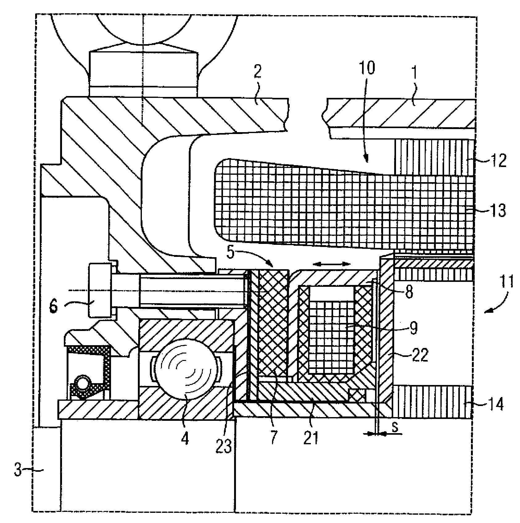
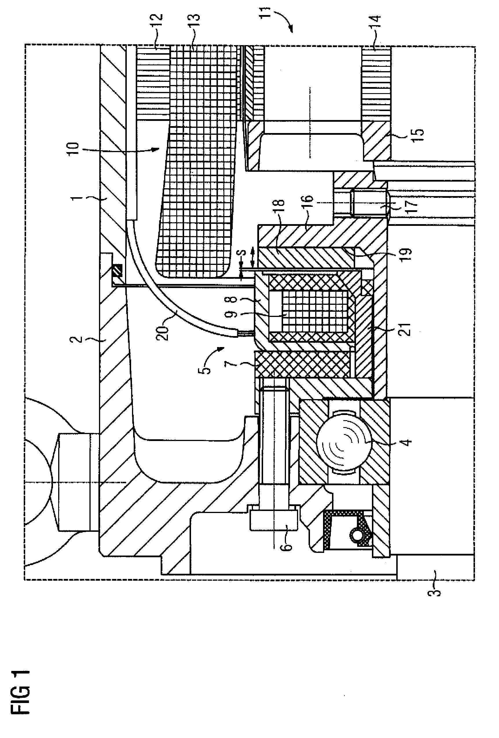
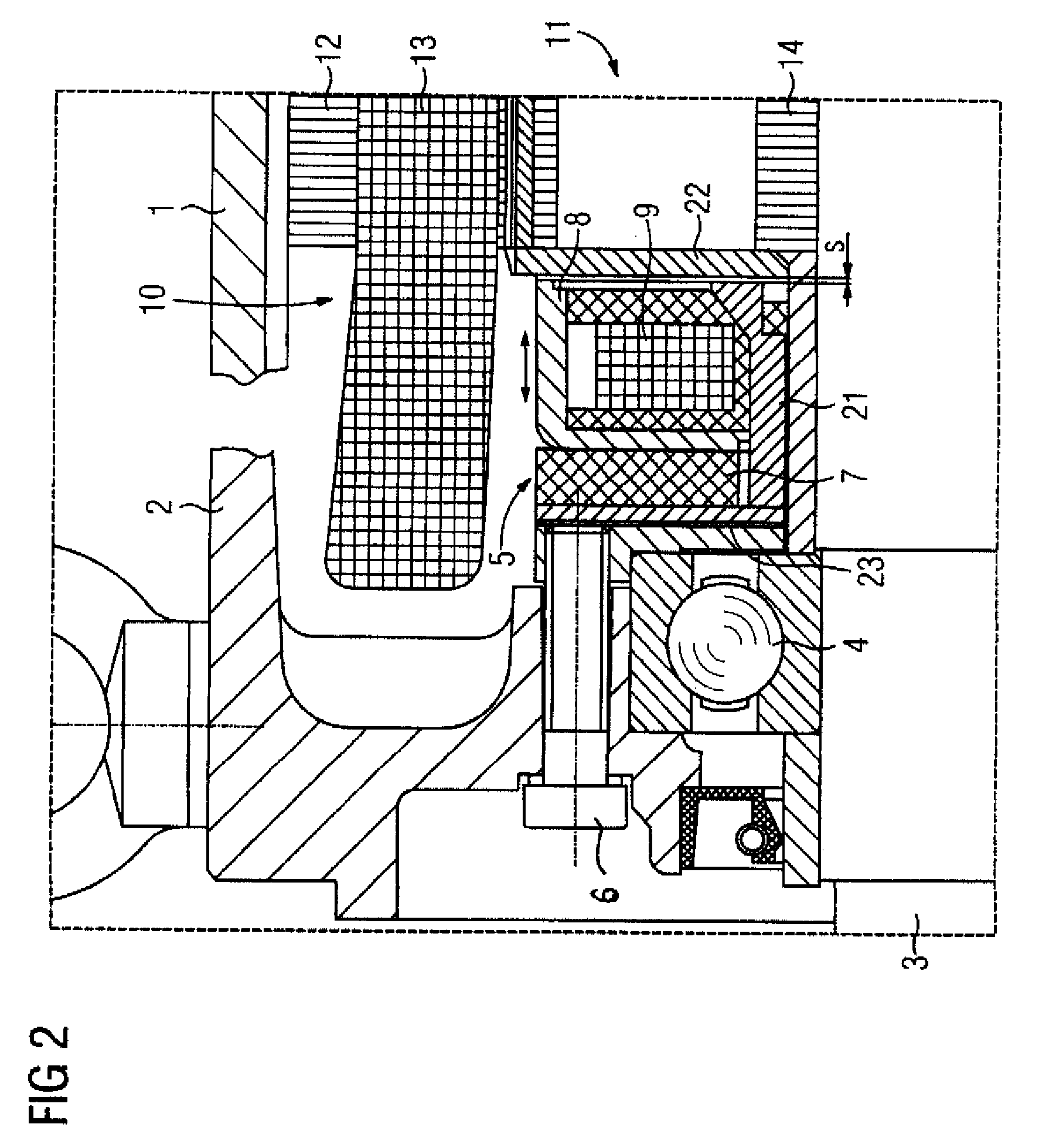
[0019]Turning now to the drawing, and in particular to FIG. 1, there is shown an embodiment of an electric motor having a housing 1 and a bearing shield 2 fixed thereto. When the electric motor has no housing, the bearing shield is normally fixed to the stator. A shaft 3 is rotatably mounted in the bearing shield with the help of a rotating bearing 4. A magnet module 5 of an...


PUM


Abstract

An electrical machine includes a stator having circumferentially arranged winding heads, with a winding head space being defined radially beneath the winding heads. Interacting with the stator is a rotor which has a rotatable laminated core. A magnetic brake is received in the winding head space and includes a magnet module having at least one permanent magnet which is axially resiliently fixed and constraint against rotation and which is magnetized in an axial direction, and an electromagnet which is arranged axially adjacent to the permanent magnet and securely fixed thereto. The electromagnet produces a magnetic field with a main direction oriented in an axial direction. Interacting with the at least one permanent magnet and the electromagnet is a ring-shaped armature which is secured directly and rigidly to the rotor so as to establish a fixed rotative engagement between the armature and the rotor.

Description

CROSS-REFERENCES TO RELATED APPLICATIONS[0001]This application claims the priority of European Patent Application, Serial No. 07022399, filed Nov. 19, 2007, pursuant to 35 U.S.C. 119(a)-(d), the content of which is incorporated herein by reference in its entirety as if fully set forth herein.BACKGROUND OF THE INVENTION[0002]The present invention relates in general to the field of electric machines.[0003]An electrical machine of a type involved here includes a housing or stator, a rotor which has a laminated core and which is rotatably mounted in the housing, and a magnetic brake. For its part, the magnetic brake has at least one permanent magnet which is fixed to the housing or stator so that it cannot rotate and is magnetized in an axial direction, an electromagnet which is arranged so that it is connected axially to the permanent magnet and is securely fixed thereto, and a ring-shaped armature which is fixed to the rotor so that it cannot rotate and acts together with the two magn...

Claims


Application Information

Patent Timeline
Patent Type & Authority Applications(United States)
IPC IPC(8): H02K7/102
CPCH02K7/1025
Inventor ECKERT, FRANK
Owner SIEMENS AG
Why Eureka
Try Eureka