
Inductor and its manufacturing method

a manufacturing method and technology of a spherical inductance, applied in the field of spherical inductance, can solve problems such as poor connection, and achieve the effect of favorable and stable manner

Active Publication Date: 2009-05-21
TAIYO YUDEN KK
View PDF3 Cites 27 Cited by
  • Summary
  • Abstract
  • Description
  • Claims
  • Application Information

AI Technical Summary

Benefits of technology

[0011]According to this inductor, stress does not generate easily at the boundary between each leader part and each terminal part wider than the leader part, even when an external force is applied to the exposed part of each terminal part or when the inductor is soldered to a circuit board, and thus the risks of generation at the aforementioned boundary of cracks that cause poor connection due to wire breakage, etc., can be eliminated and consequently the connection relationship between the leader part and terminal part can be maintained in a favorable manner.
[0013]According to this inductor manufacturing method, the aforementioned inductor can be manufactured in a favorable and stable manner.

Problems solved by technology

Since the aforementioned inductor has a structure where each terminal part of the coil is exposed entirely and also the boundary between each leader part and each terminal part wider than the leader part is exposed from the magnetic body, there are risks that cracks that cause poor connection due to wire breakage, etc., may generate at the aforementioned boundary if an external force is applied to each exposed terminal part or when the inductor is soldered to a circuit board.

Method used


Image

  • Inductor and its manufacturing method
  • Inductor and its manufacturing method
  • Inductor and its manufacturing method

Examples


embodiment 1

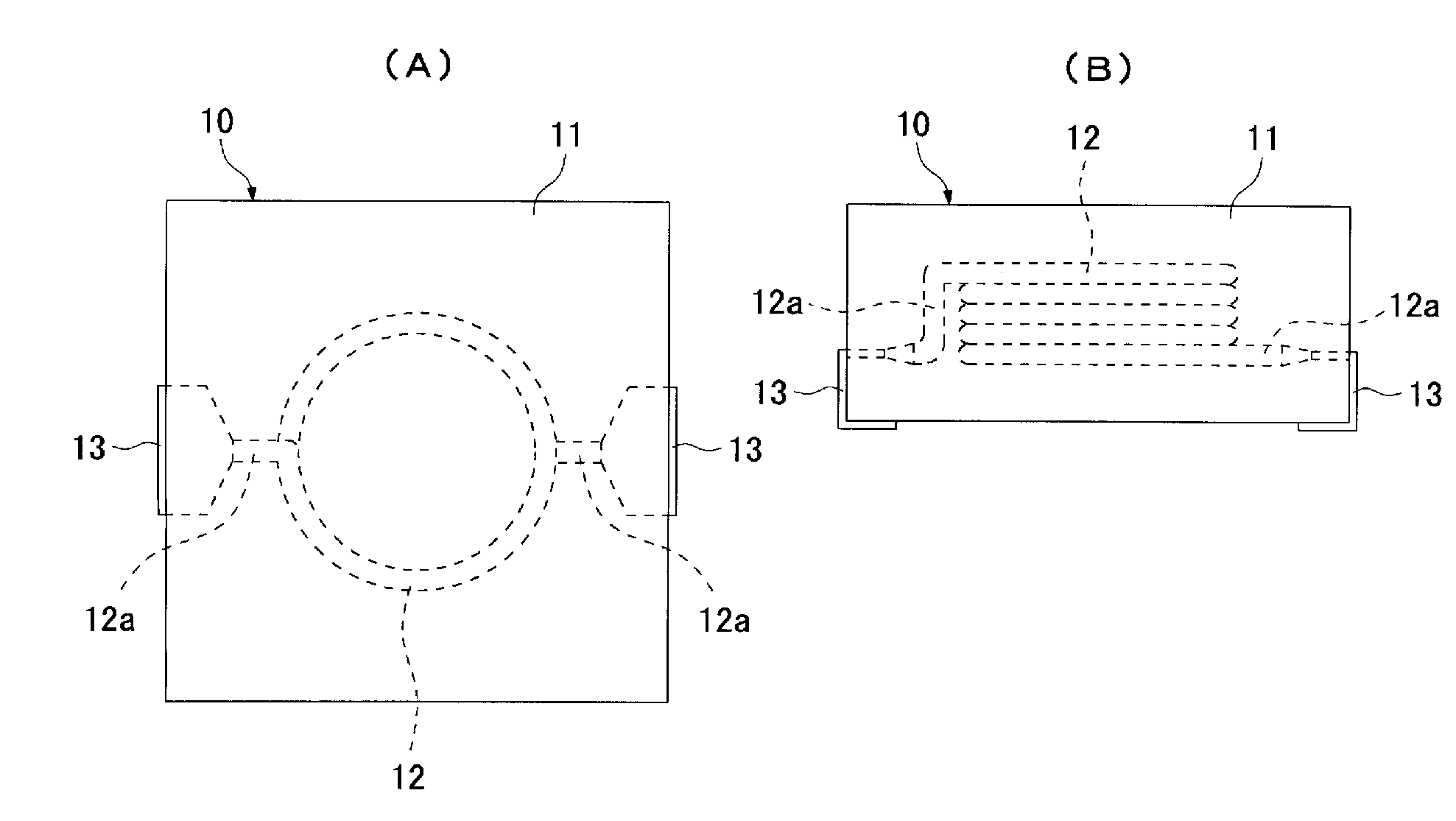
[0059]FIGS. 1 (A) and 1 (B) provide a top view and side view, respectively, of an inductor which illustrates an embodiment of the present invention.

[0060]The inductor 10 shown in these figures has a magnetic body 11 of a rectangular solid shape and a coil 12 buried in the magnetic body 11.

[0061]The magnetic body 11 is formed by pressure-forming a magnetic body material to a rectangular solid shape and then curing the formed body. For your information, examples of magnetic body materials currently in use include, among others, known materials such as those that include at least permalloy, sendust or other magnetic metal powder, or epoxy, phenol, silicone or other binding agent.

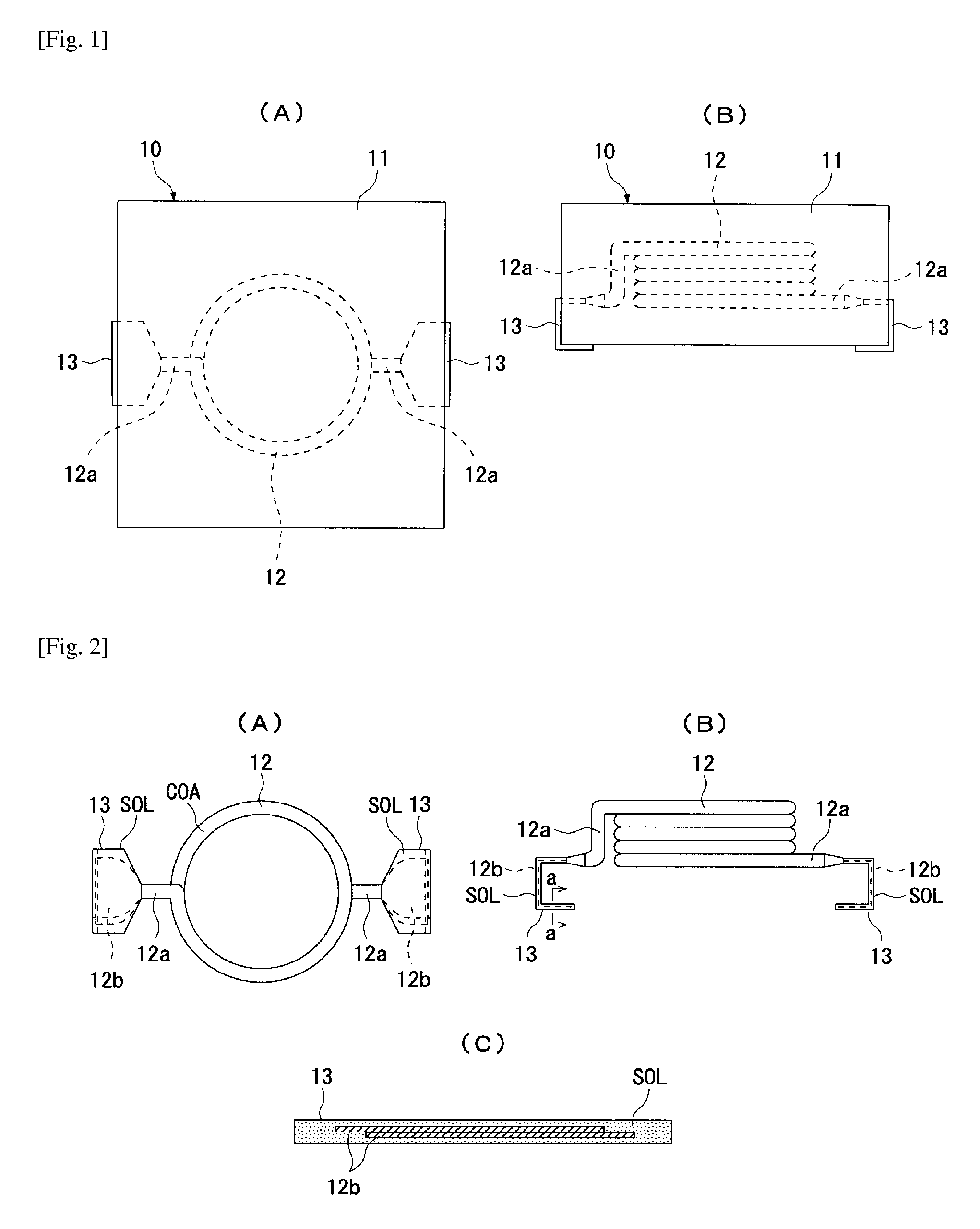
[0062]The coil 12, whose top view, side view and enlarged cross-section view of the terminal (enlarged cross-section view of a-a) are shown in FIGS. 2 (A) to 2 (C), consists of a metal wire made of copper, etc., and a part constituted by a helically wound coil wire (no applicable symbol) having urethane, polyim...

embodiment 2

[0110]FIGS. 26 (A) to 26 (C) provide a top view, bottom view and side view, respectively, of an inductor which illustrates another embodiment of the present invention.

[0111]The inductor 20 shown in these figures has a magnetic body 21 of a rectangular solid shape and a coil 22 buried in the magnetic body 21.

[0112]The magnetic body 21 is formed by pressure-forming a magnetic body material to a rectangular solid shape and then curing the formed body. For your information, examples of magnetic body materials currently in use include, among others, known materials such as those that include at least permalloy, sendust or other magnetic metal powder, or epoxy, phenol, silicone or other binding agent.

[0113]The coil 22, whose top view, side view and enlarged cross-section view of the terminal (enlarged cross-section view of b-b) are shown in FIGS. 27 (A) to 27 (C), consists of a metal wire made of copper, etc., and a part constituted by a helically wound coil wire (no applicable symbol) ha...


PUM

PropertyMeasurementUnit
widthaaaaaaaaaa
magneticaaaaaaaaaa
shapeaaaaaaaaaa

Abstract

An inductor 10 has a magnetic body 11 of a rectangular solid shape and a coil 12 embedded in the magnetic body 11. The coil 12 integrally has a part constituted by a helically wound coil wire, two leader parts 12a provided at the two ends of the wound part, and terminal parts 13 connected to the ends of the leader parts and wider than the leader parts 12a, where the boundary between each leader part 12a and each terminal part 13 is positioned in the magnetic body 11, and the end of each terminal part 13 is exposed from the corresponding side face of the magnetic body 11 and folded in an L shape along the side face and bottom face.

Description

BACKGROUND OF THE INVENTION[0001]1. Field of the Invention[0002]The present invention relates to an inductor structured in such a way that a coil is buried in a magnetic body, and a method for manufacturing said inductor.[0003]2. Description of the Related Art[0004]This type of inductor has a magnetic body of a specified shape and a coil buried in the magnetic body.[0005]As described in Patent Literatures 1 and 2, coils having the aforementioned structure and currently in use include those that integrally have a part constituted by helically wound coil wire, two leader parts provided at the two ends of the wound part and terminal parts connected to these leader parts and wider than the leader parts. With these coils, when a magnetic body material is pressure-formed to a specified shape the coil is buried in the formed body so that each terminal part will be exposed entirely from the formed body, while each terminal part exposed from the formed body is bent at the boundary between th...

Claims


Application Information

Patent Timeline
Patent Type & Authority Applications(United States)
IPC IPC(8): H01F27/02H01F41/04
CPCH01F17/04Y10T29/49071H01F2017/048
Inventor YAGASAKI, TOSHIYUKIKASHIWA, TOMOOOGAWA, HIDEKIWADA, KOUICHIROUOKINO, YOSHIKAZUTOSAKA, SHOICHI
Owner TAIYO YUDEN KK
Learn More