Gas station television

a technology for gas station television and cooling system, applied in the direction of cooling/ventilation/heating modification, electrical equipment, instruments, etc., can solve the problems of insufficient heat dissipation system of the past, the market is demanding a larger screen size for the display, and the insufficient climate of many climates, so as to reduce the amount of heat

Inactive Publication Date: 2009-05-21
MFG RESOURCES INT INC
View PDF10 Cites 68 Cited by
  • Summary
  • Abstract
  • Description
  • Claims
  • Application Information

AI Technical Summary

Benefits of technology

[0011]Provided a fan is included, the display and system may further include an optional air curtain device to reduce the amount of heat on the surface of the dis

Problems solved by technology

By itself, this is not adequate in many climates, especially when radiative heat transfer from the sun through a display window becomes a major factor.
Furthermore, the market is demanding larger screen sizes for displays.
With increased heat production with the larger screens and radiat

Method used


Image

  • Gas station television
  • Gas station television
  • Gas station television

Examples


Embodiment Construction

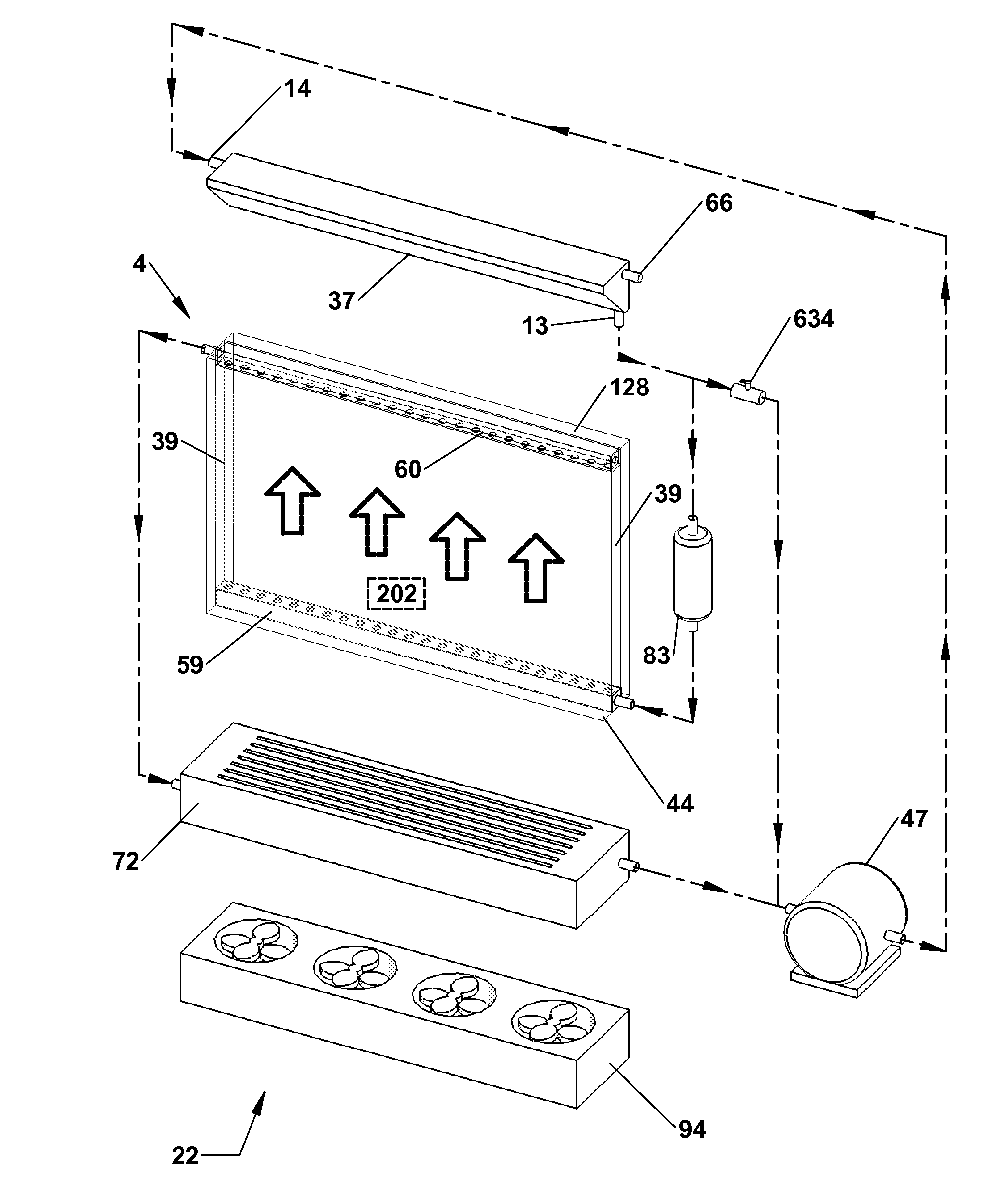
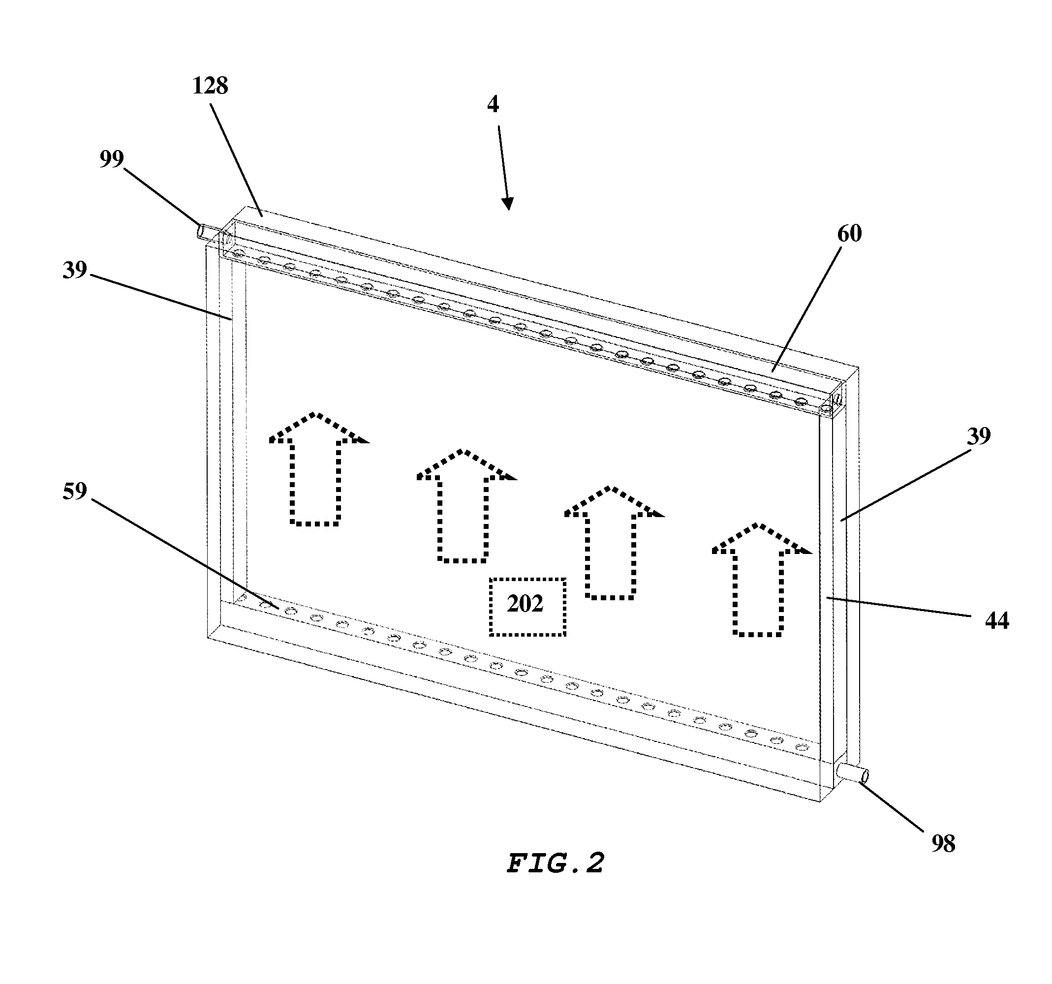
[0021]Embodiments of the present invention relate to a cooling system for an electronic display and to combinations of the cooling system and the electronic display.

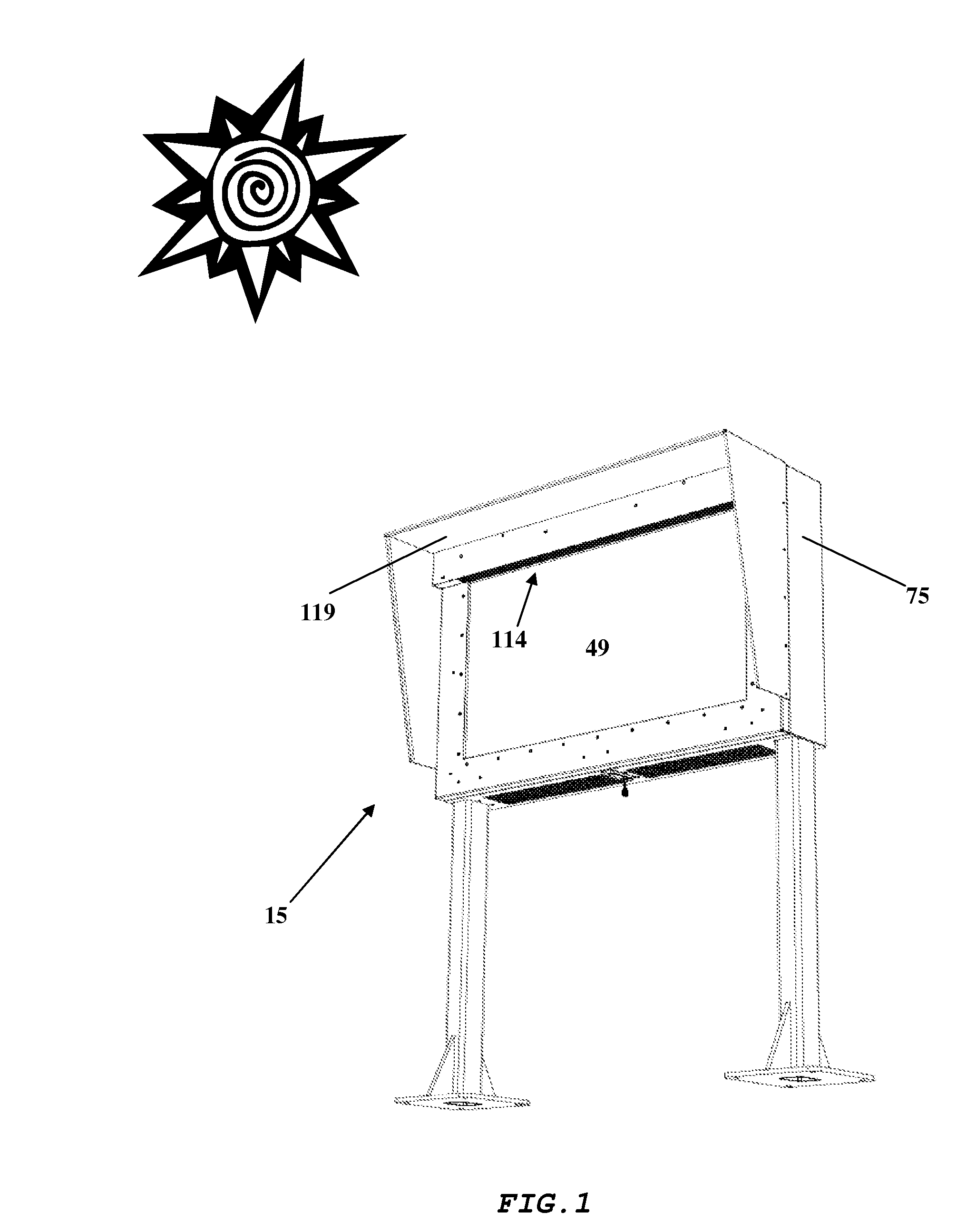
[0022]FIG. 1 shows an exemplary embodiment of the present invention. As may be appreciated, when the display 15 is exposed to outdoor elements, the temperatures inside the display 15 will vary greatly without some kind of cooling device. As such, the electronics including the display screen (e.g., LCD screen) will have a greatly reduced life span. By implementing certain embodiments of the cooling system disclosed herein, temperature fluctuation is greatly reduced. This cooling capability has been achieved in spite of the fact that larger screens generate more heat than smaller screens.

[0023]Because the display 15 has an innovative cooling system, it may be placed in direct sunlight. Although the cooling system may be used on smaller displays, it is especially useful for larger LCD, LED, or organic light emitting diodes ...


PUM


Abstract

Preferred embodiments relates to a cooling system and a method for cooling an electronic display. Embodiments include a transparent liquid cooling chamber, a reservoir tank, and a pump. The components in the system are preferably housed within the electronic display housing. The cooling chamber defines a fluid compartment that is anterior to and coextensive with the electronic display surface. Circulating coolant removes heat directly from the electronic display surface by advection. In order to view the display, the coolant fluid is transparent or at least semi-transparent. The image quality of an exemplary embodiment remains essentially unchanged, even though coolant is flowing over the visible face of the electronic display surface.

Description

CROSS-REFERENCE TO RELATED APPLICATIONS[0001]This application is a non-provisional patent application and claims priority to co-pending application Nos. 61 / 033,058 filed Mar. 3, 2008; 61 / 033,064 filed Mar. 3, 2008; 61 / 054,717 filed May 16, 2009; and 61 / 057,599 filed May 30, 2008, which are herein incorporated in their entirety. This application is a Continuation-in-part of U.S. application Ser. No. 11 / 941,728 filed Nov. 16, 2007, which is herein incorporated in its entirety.TECHNICAL FIELD[0002]This invention generally relates to cooling systems and in particular to cooling systems for electronic displays.BACKGROUND OF THE ART[0003]Conductive and convective heat transfer systems for electronic displays are known. These systems of the past generally attempt to remove heat from the electronic components in a display through as many sidewalls of the display as possible. In order to do this, the systems of the past have relied primarily on fans for moving air past the components to be c...

Claims


Application Information

Patent Timeline
IPC IPC(8): H05K7/20
CPCH05K7/20972
Inventor DUNN, WILLIAM
Owner MFG RESOURCES INT INC
Why Eureka
Try Eureka