Pumping unit for delivery of liquid medium from a vessel

Inactive Publication Date: 2009-05-21
ICECURE MEDICAL
View PDF102 Cites 13 Cited by
  • Summary
  • Abstract
  • Description
  • Claims
  • Application Information

AI Technical Summary

Benefits of technology

[0040]In addition, a sensing unit supplies to the power-control unit data regarding an angle and direction of inclination of the Dewar flask. For example, two clinometers can play a role of such sensing unit. In such a way, in accordance to the data of the sensing unit, the power-control unit energizes the electrical heating unit, which is related at a certain moment to the branch with its proximal end immersed into liquid cryogen (for example, into LNG). A bellows' section can be incorporated into each branch in order to provide required flexibility to this construction.

Problems solved by technology

Each of the above patents teach a proposed solution which is not useful for cryogenic devices, but instead is only useful for the taught application.

Method used


Image

  • Pumping unit for delivery of liquid medium from a vessel
  • Pumping unit for delivery of liquid medium from a vessel
  • Pumping unit for delivery of liquid medium from a vessel

Examples


Embodiment Construction

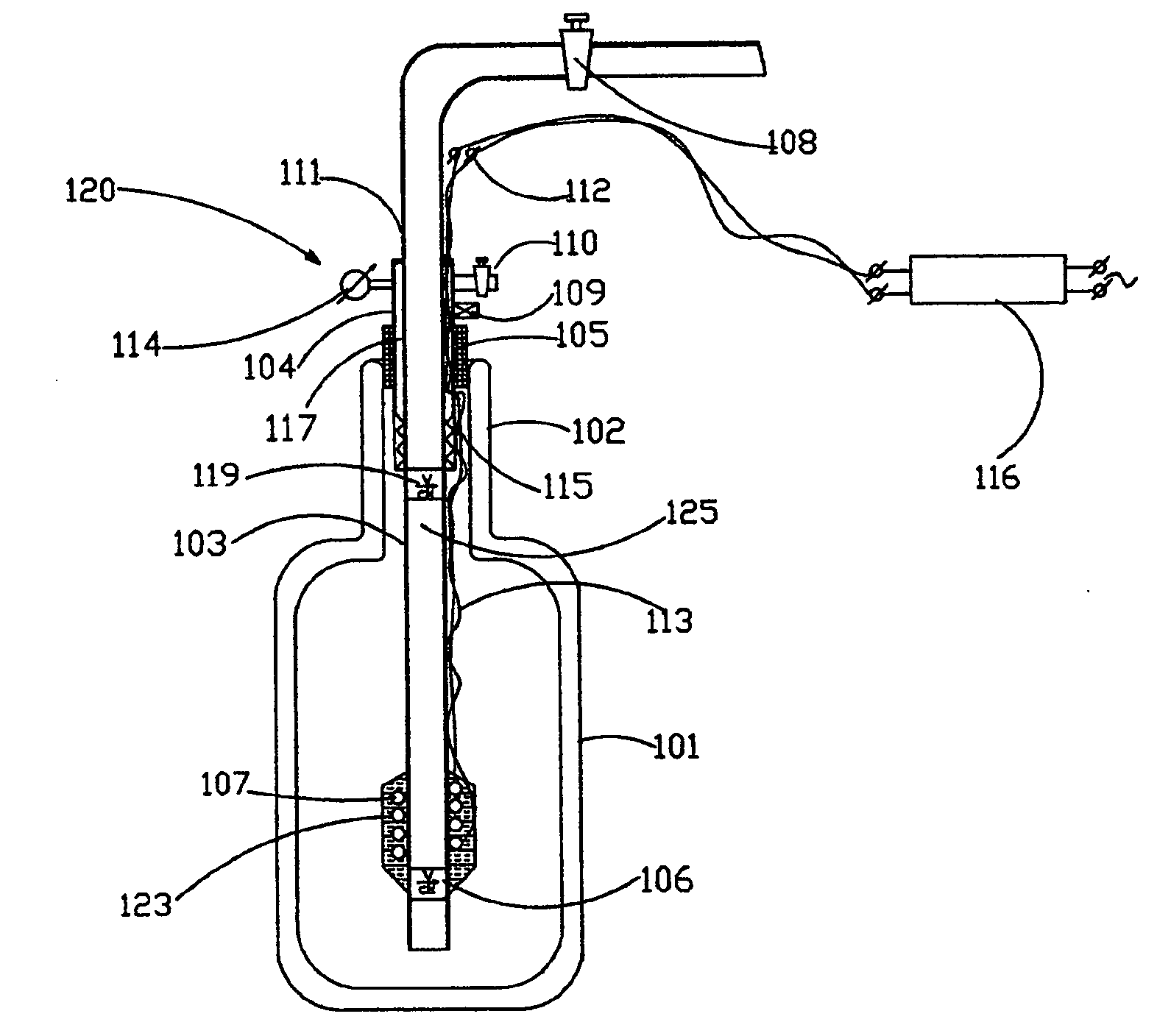
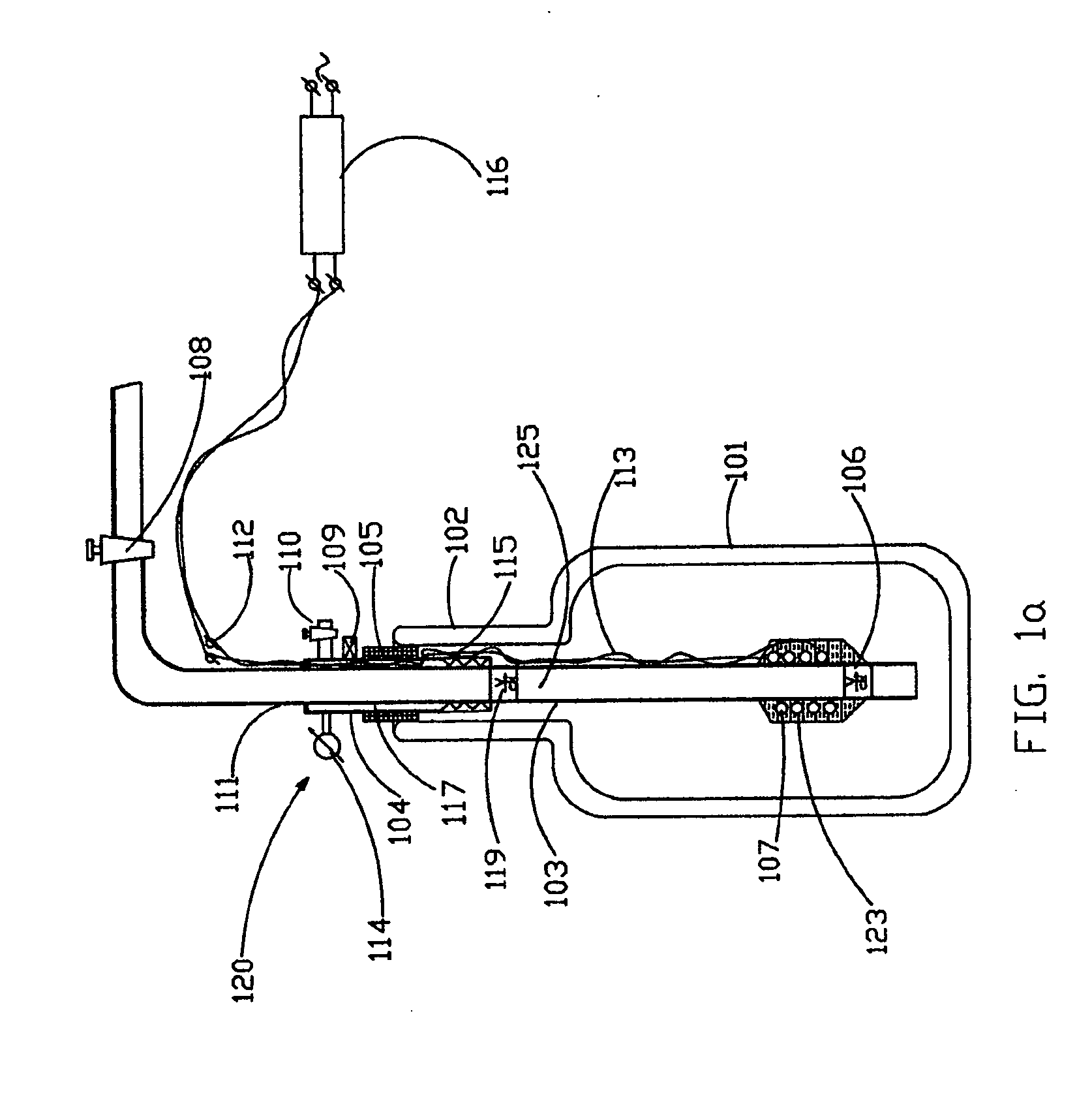
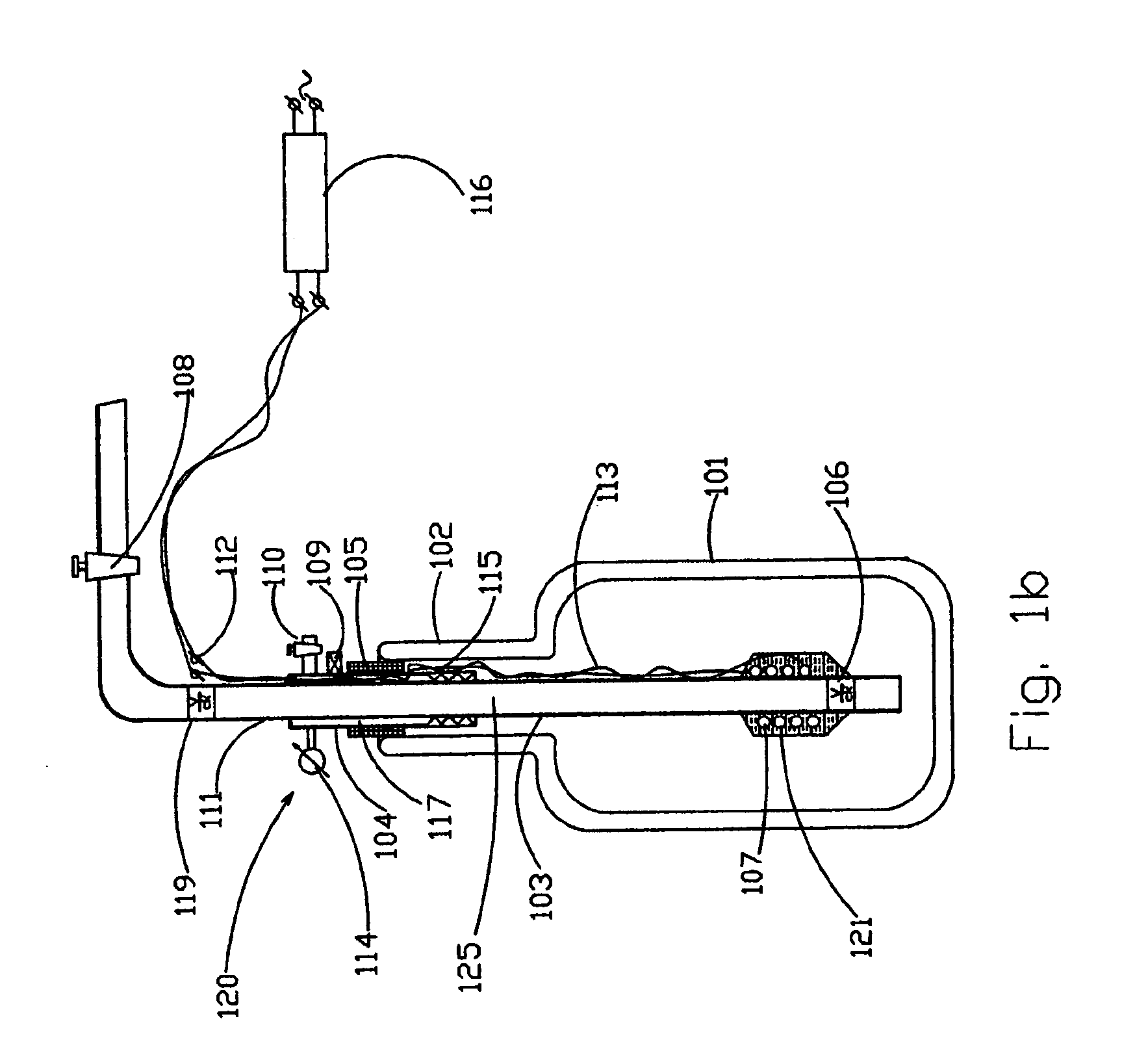
[0050]FIG. 1a shows a Dewar flask 101 with neck 102, which is intended to be filled with a liquid cryogen to be supplied by the pumping unit 120. Pumping unit 120 comprises a central feeding conduit 103 for supplying the liquid cryogen to an external location, and jacket 104 surrounding the central feeding conduit 103 with gap 117 formed between them. The central feeding conduit 103 comprises an external section 111. The upper edge of jacket 104 is sealed with the central feeding conduit 103 as shown. An annular rubber ring 105 is installed on jacket 104 and inserted partially into neck 102, for holding pumping unit 120 in Dewar flask 101 and for sealing jacket 104 to the Dewar flask 101. Also, preferably a shut-off valve 108 is installed on the external section 111 of the central feeding conduit 103. The shut-off valve 108 ensures control of the supply of the liquid cryogen.

[0051]In a preferred embodiment, preferably safety and relief valves 109 and 110 are installed on ports of th...


PUM


Abstract

A pumping unit for delivering a liquid medium from a low pressure vessel such that the delivered medium has sufficiently high pressure, by providing the liquid medium in the form of separated pulses.

Description

FIELD OF THE INVENTION[0001]The invention relates to a pumping unit and, in particular, to a high pressure pump, for example for delivery of a liquid medium such as liquid cryogen from a vessel with sufficiently high pressure, while maintaining low pressure in the vessel itself.BACKGROUND OF THE INVENTION[0002]There are some US patents describing pumping systems, which operate on the basis of a geyser principle.[0003]U.S. Pat. No. 4,552,208 describes an apparatus and method for circulating a heat transfer liquid from a heat collector to a heat exchanger which is located at a level below that of the heat collector by at least partially vaporizing the heat transfer liquid in the steeply sloped collector and the vapor / liquid rises in a series of “slugs” to a condenser located adjacent the top end thereof. The vapor is condensed and the hot liquid is forced downwardly to the heat exchanger by the pressure of the rising slugs of vapor and liquid. After giving up useful heat in the heat e...

Claims


Application Information

Patent Timeline
Patent Type & Authority Applications(United States)
IPC IPC(8): F04B19/24
CPCF04B15/08F04F1/18F04F1/04F04B19/24
Inventor TOUBIA, DIDIERLEVIN, ALEXANDERKAGANOVICH, MIRON
Owner ICECURE MEDICAL
Why Eureka
Try Eureka