Multi-Channel Flow Cells

a flow cell and multi-channel technology, applied in the field of microfluidic flow cells, can solve problems such as complex processes to be carried out, and achieve the effect of reducing cross-contamination in sample loading

Inactive Publication Date: 2009-05-21
FLUIDIGM CORP
View PDF0 Cites 18 Cited by
  • Summary
  • Abstract
  • Description
  • Claims
  • Application Information

AI Technical Summary

Benefits of technology

[0004]In one embodiment, a two-sided multi-channel flow cell receives multiple analyte samples in a manner that prevents contamination between the samples. The flow cell has multiple independently-addressable sample channels and uses removable loading blocks for loading sample. The flow cell can form a well for housing an index-matched fluid for observation and analysis of analytes within the multiple flow channels. Each of the flow channels has an inlet and an outlet which mate, respectively, with the loading block and an outlet block and which are also accessible for introduction of chemical reagents after the loading and outlet blocks are removed.
[0005]Embodiments of flow cells according to the invention allow for reduced cross-contamination in sample loading and the ability to observe activity within the flow cell once the channels are loaded. They also are useful for chemical analysis in which optical detection is required.

Problems solved by technology

For example, microfluidic systems permit complicated processes to be carried out using small amounts of reagents.

Method used


Image

  • Multi-Channel Flow Cells
  • Multi-Channel Flow Cells
  • Multi-Channel Flow Cells

Examples


Embodiment Construction

and example.

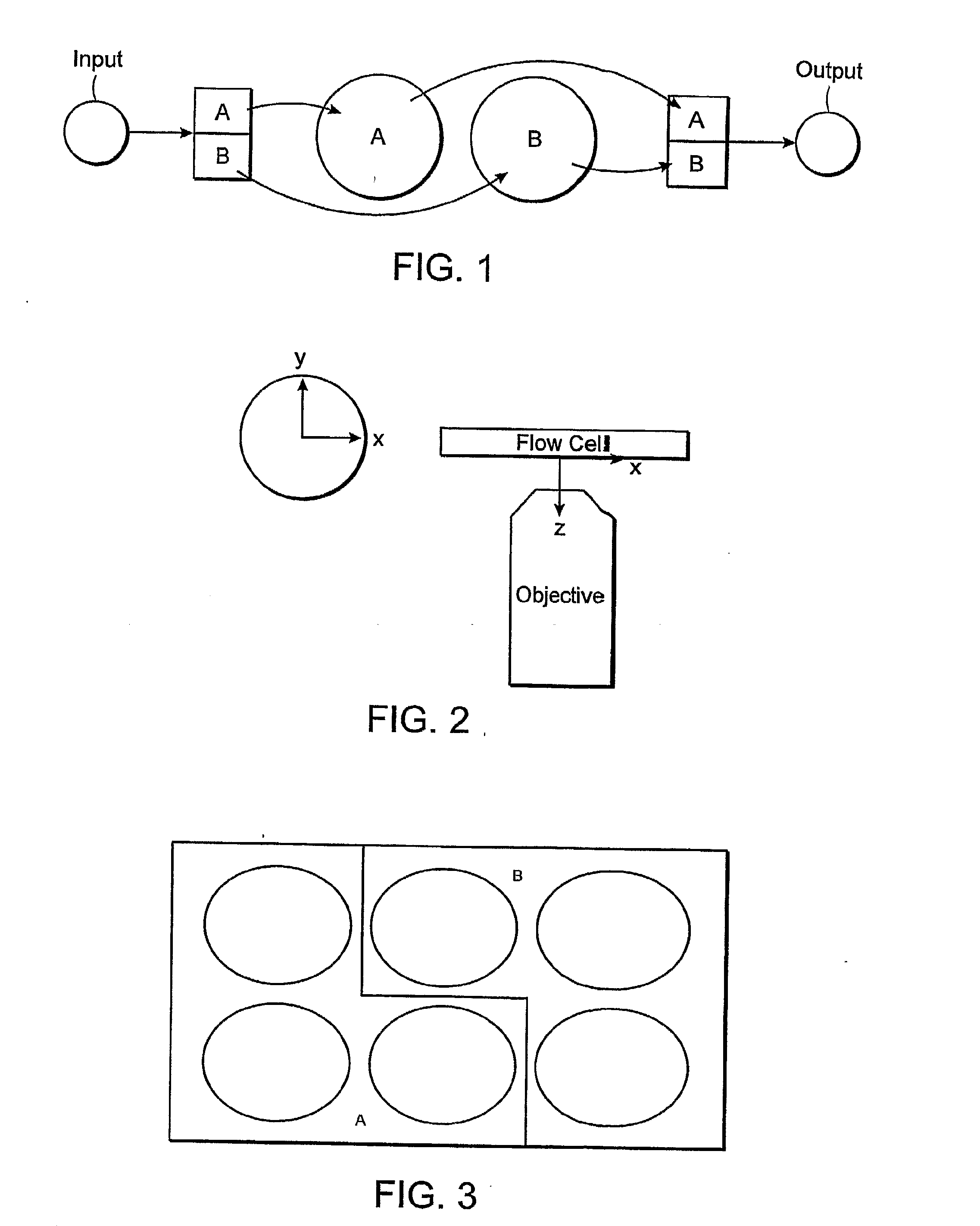
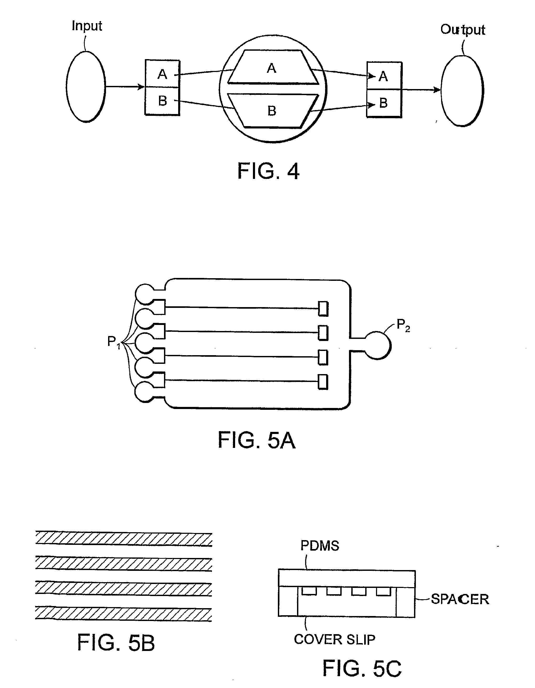
[0127]The invention is described in the context of a template-dependent sequencing-by-synthesis reaction. Generally, the reaction comprises attaching template / primer duplex to an epoxide surface of two or more imaging areas as described above. Parallel sequencing-by-synthesis reactions are conducted on the surface of one imaging area using optical detection of incorporated nucleotides of a second imaging area followed by sequence compilation of both imaging areas. Either de novo sequencing or resequencing of a reference sequence is possible using methods of the invention. Partial sequencing can also be conducted using methods of the invention as will be apparent to those of ordinary skill in the art upon consideration of the disclosure herein. In a preferred embodiment, single duplex molecules are sequenced in parallel by placing them on the epoxide surface and confirming their locations. In that embodiment, only duplex that is optically-isolated from other duplex is use...


PUM


Abstract

A multi-channel flow cell can allow for reduced cross-contamination in sample loading and the ability to observe activity within the flow cell once the channels are loaded. A multi-channel flow cell includes a plurality of independently-addressable channels sandwiched between a two substrates. Each of the channels can be coated with a layer that facilitates support-binding of an analyte. Each of the channels terminates on one end in an inlet and on the other end in an outlet. A loading block having inlet ports that match the inlets of the channels can be mated to the inlets of the channels, and an outlet block can be mated to the outlets of the channels. Analytes can be introduced into the channels via the inlet ports of the loading block and are pulled through the channels by capillary action or by vacuum. Once analyte has been introduced into each of the channels, the loading and outlet blocks can be removed and the device turned over Such a flow cell can be used for streamlining the process of reaction and interrogation of biochemical assays at the microfluidic level. Reagents can be introduced into each of the channels of the flow cell for chemical reactions therein, excess reagent being washed out through the channel outlets. Observation of optically-detectable moieties is then conducted. With such a flow cell optical labels associated with incorporation in a sequencing-by-synthesis reaction can be observed.

Description

TECHNICAL FIELD[0001]The invention relates generally to microfluidic flow cells, and also to performing biochemical assays using such cells.BACKGROUND INFORMATION[0002]Fluidic systems are used in a variety of technical areas including biochemical analysis, medical diagnostics, analytical chemistry, chemical synthesis, and environmental monitoring. Microfluidic systems provide certain advantages in acquiring chemical and biological information. For example, microfluidic systems permit complicated processes to be carried out using small amounts of reagents.SUMMARY OF THE INVENTION[0003]The invention generally relates to flow cells, particularly multi-channel flow cells, and methods for using the flow cells that streamline the process of reaction and interrogation of biochemical assays at the microfluidic level. One or more samples can be loaded and analyzed with such a flow cell.[0004]In one embodiment, a two-sided multi-channel flow cell receives multiple analyte samples in a manner ...

Claims


Application Information

Patent Timeline
Patent Type & Authority Applications(United States)
IPC IPC(8): B01J19/00
CPCB01J2219/00522G01N2021/0346B01J2219/00621B01L3/5025B01L3/502715B01L3/502761B01L2200/027B01L2300/0636B01L2300/0816B01L2300/0829B01L2300/0877B01L2300/0887B01L2300/16B01L2300/163B01L2400/0406B01L2400/049G01N21/05G01N35/1095B01J2219/00605
Inventor LAWSON, JOHNWELLSMAN, PARRISKIANI, SEPEHR
Owner FLUIDIGM CORP
Why Eureka
Try Eureka