Fuel cell

a fuel cell and cell technology, applied in the field of fuel cells, can solve problems such as gaps (clearances) created

Inactive Publication Date: 2009-05-21
TOYOTA JIDOSHA KK
View PDF3 Cites 8 Cited by
  • Summary
  • Abstract
  • Description
  • Claims
  • Application Information

AI Technical Summary

Benefits of technology

[0008]The invention provides a fuel cell that prevents the escaping flow of reaction gases toward the gaps.

Problems solved by technology

However, in the fuel cell with the porous members and the seal gasket described in JP-A-2002-231274, gaps (clearances) are created, for structural reasons, between the separator, the seal gasket, and the outer peripheral surfaces of the porous members.

Method used


Image

  • Fuel cell
  • Fuel cell
  • Fuel cell

Examples


Embodiment Construction

[0029]Hereinafter, example embodiments of the invention will be described in detail with reference to the drawings.

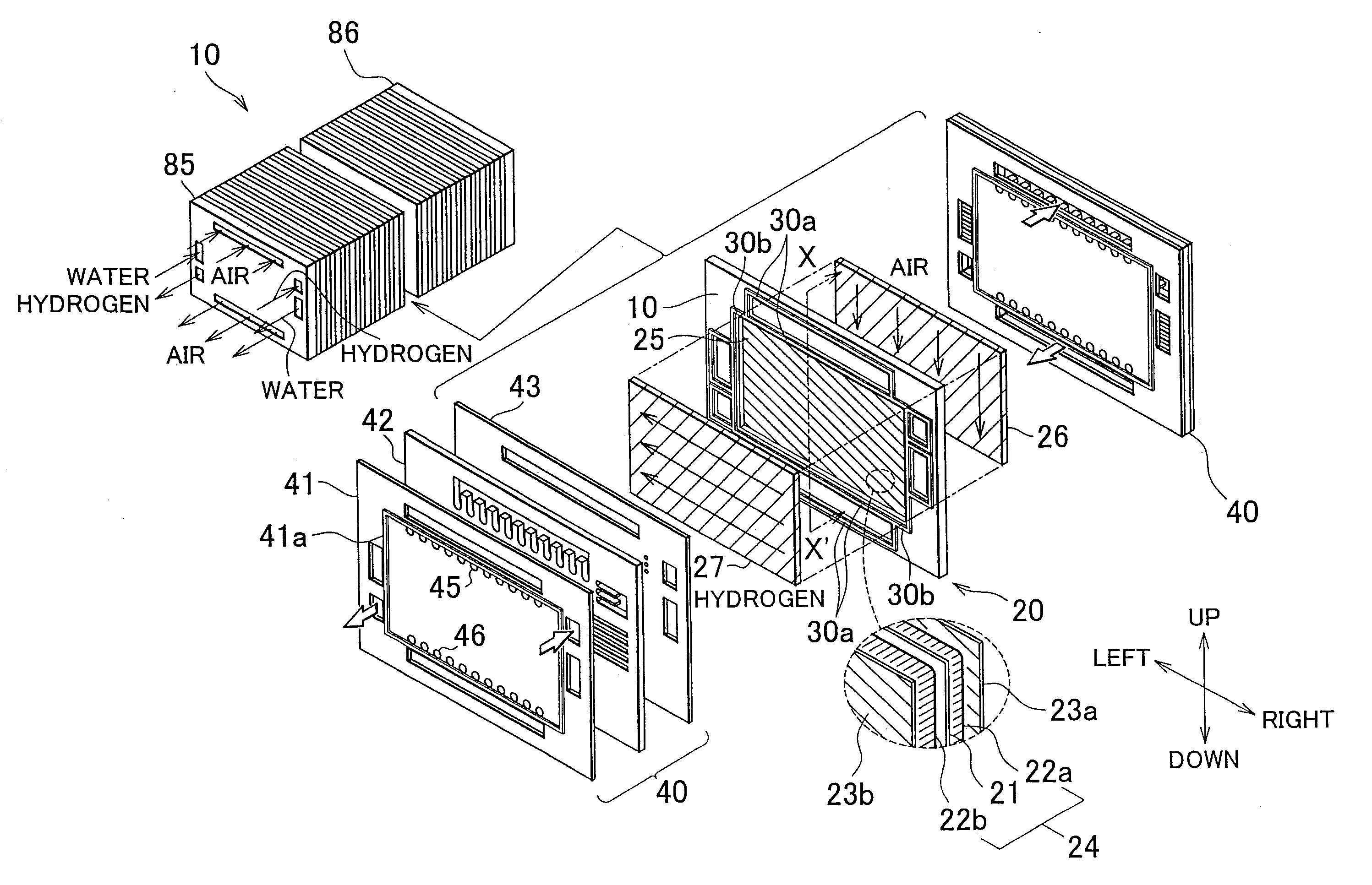
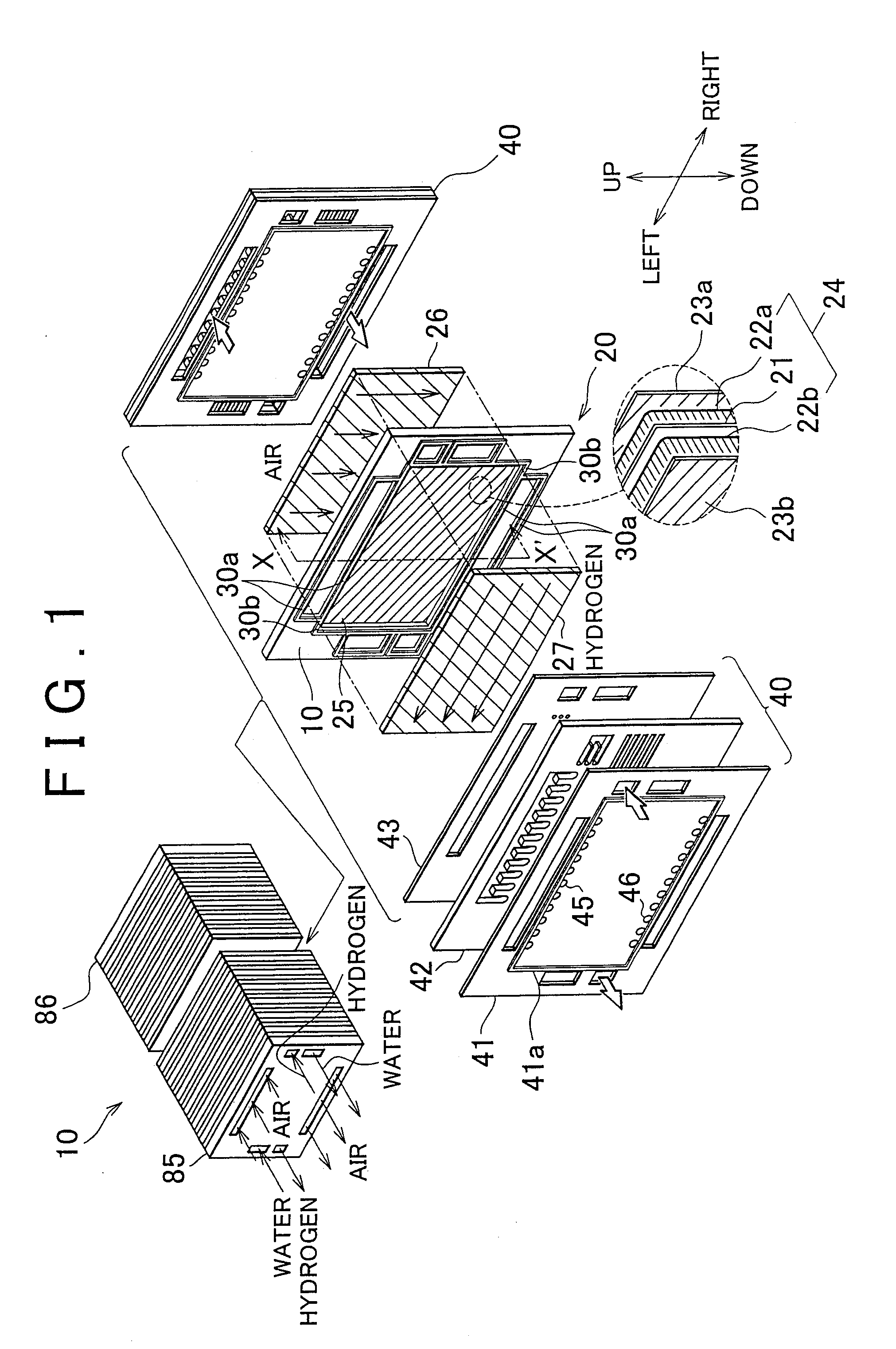
[0030]FIG. 1 is a view schematically showing the configuration of a fuel cell 10 according to the first example embodiment of the invention. The fuel cell 10 is a polymer electrolyte fuel cell that is supplied with hydrogen gas and air and generates electric power through electrochemical reaction between hydrogen and oxygen. The fuel cell 10 is mounted in a vehicle and used as the power source for producing the drive power for the vehicle.

[0031]Referring to FIG. 1, the fuel cell 10 mainly includes: a power generating portion 20 that has an electrolytic membrane 21; porous members 26, 27 that serve as reaction gas passages where air and hydrogen gas (hereinafter, referred to as “reaction gases”) flow; and a separator 40 that collects the electric power generated through the electrochemical reaction and also serves as partition walls. In the fuel cell 10, the separator 40...


PUM

PropertyMeasurementUnit
porosityaaaaaaaaaa
porosityaaaaaaaaaa
currentaaaaaaaaaa

Abstract

Ribs (41a, 43a) are formed on a cathode plate (41) and an anode plate (43) of a fuel cell (10). The ribs (41a, 43a) protrude toward a contact surface of porous members (26, 27), and provided along an outer periphery of the porous members (26, 27) to surround the outer periphery of the porous members (26, 27). The rib (41a) of the cathode plate (41) and the rib (43a) of the anode plate (43) are arranged to face each other when separator (40) and the porous members (26, 27) are stacked on both sides of a power generating portion (20). The power generating portion (20), the porous members (26, 27), and the separator (40) are stacked such that a seal gasket (30) on the power generating portion (20) is partially sandwiched between the ribs (41a, 43a).

Description

BACKGROUND OF THE INVENTION[0001]1. Field of the Invention[0002]The invention relates to a fuel cell that is supplied with reaction gases and generates electric power using the supplied reaction gases.[0003]2. Description of the Related Art[0004]Typically, a fuel cell stacks alternately a power generating portion that has an electrolytic membrane and electrode catalyst layers, and a separator that serves as partition wall. A variety of structures of the fuel cell have been proposed.[0005]For example, a structure of the fuel cell has been proposed in which porous members with a predetermined porosity are used as gas flow passages, and the reaction gases for power generation are supplied to the power-generating portion via the porous members. The fuel cell is provided with a seal gasket that has a lip portion (i.e., seal line) for preventing leaks of the reaction gases, on the outer periphery of the power-generating portion. Incidentally, the porous members are arranged on both sides ...

Claims


Application Information

Patent Timeline
Patent Type & Authority Applications(United States)
IPC IPC(8): H01M2/14H01M8/10
CPCH01M8/0206H01M8/0228H01M8/023Y02E60/50H01M8/0271H01M8/241H01M8/242H01M8/0254H01M8/2483H01M8/0273
Inventor SATO, HIROMICHIKAJIWARA, TAKASHIHOTTA, YUTAKAFUTAMI, SATOSHI
Owner TOYOTA JIDOSHA KK
Why Eureka
Try Eureka