Receiving device and decoding method thereof

a decoding method and receiving device technology, applied in the direction of coding, code conversion, fault response, etc., can solve the problems of large circuit scale, high consumption of power, long decoding process maximum number of repetitions, etc., and achieve the effect of reducing the number of mounted decoders

Inactive Publication Date: 2009-05-21
FUJITSU LTD
View PDF11 Cites 113 Cited by
  • Summary
  • Abstract
  • Description
  • Claims
  • Application Information

AI Technical Summary

Benefits of technology

[0015]Taking the aforementioned problem into consideration, it is the object of the present invention to prevent a worsening of the error characteristics even though the number of mounted decoders is reduced.
[0017]The present invention is a receiving device and a decoding method thereof in a communication system in which a transmitter separates one frame of information bits into plural of blocks, encodes the information bits of each block using code that reduces errors in the decoding results after each time decoding process is repeated and transmits blocks, and the receiving device receives the encoded information bits of each block, and decodes the encoded information bits to the information bits before encoding.
[0018]The decoding method of the present invention includes: a step of providing a receiving device with plural of decoders number of which is less than the number of blocks per frame, and presetting a maximum number of repetitions that decoding is performed by each decoder; a step of expressing the encoded information bits of each received block using likelihood in each decoder; a step of performing a decoding process on the encoded information bits of each received block expressed by likelihood, and judging whether a condition for stopping decoding has been met after each decoding process; and a step of saving the decoding results when the condition for stopping decoding has been met, and executing the decoding process for the encoded information bits of a different block for which the decoding process has not yet been performed.
[0023]The decoding method above further comprising: a step of causing the decoders to start the decoding process in order after the decoding process becomes possible for the encoded information bits of each block, and a step of increasing the maximum number of repetitions of the decoder that starts the decoding process at first more than the maximum number of repetitions of other decoders.

Problems solved by technology

However, in conventional processing, there is a problem in that the processing time in order to perform the decoding process the maximum number of repetitions becomes long, and the consumed power becomes high.
However, since a conventional receiver has the same number of decoders as the number of code blocks, there is a problem in that the scale of the circuit becomes large.

Method used


Image

  • Receiving device and decoding method thereof
  • Receiving device and decoding method thereof
  • Receiving device and decoding method thereof

Examples


first embodiment

(B) First Embodiment

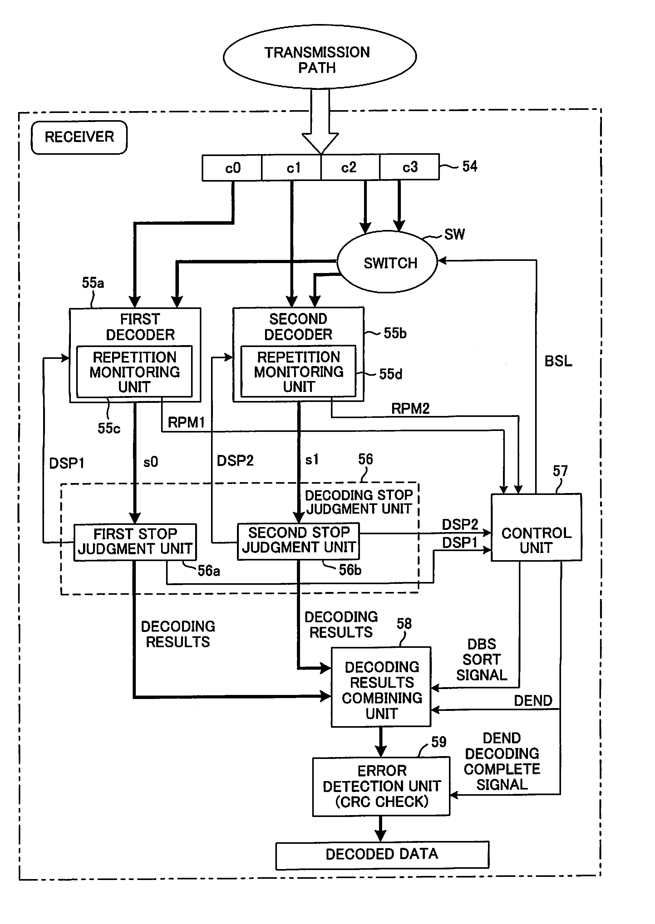
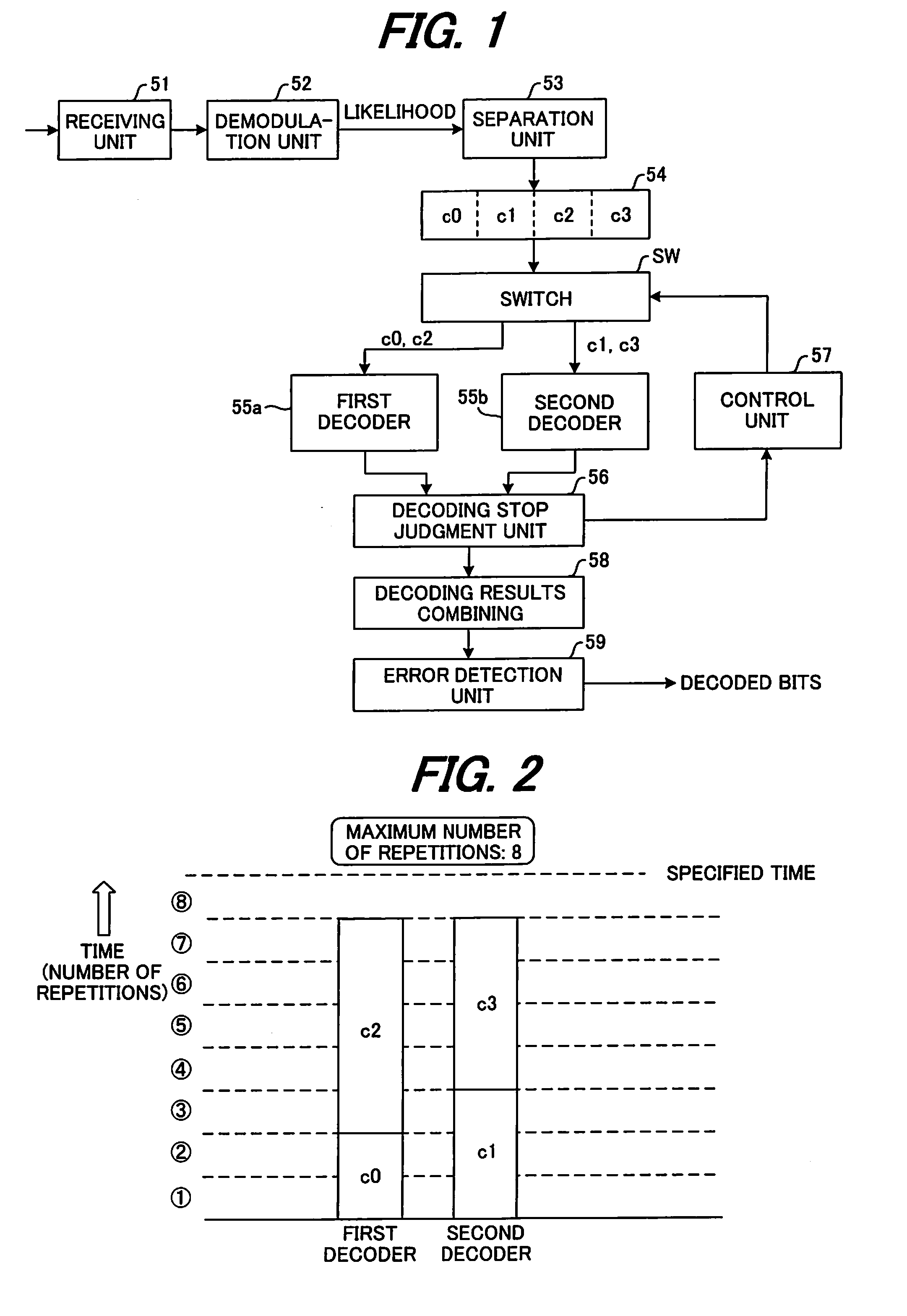
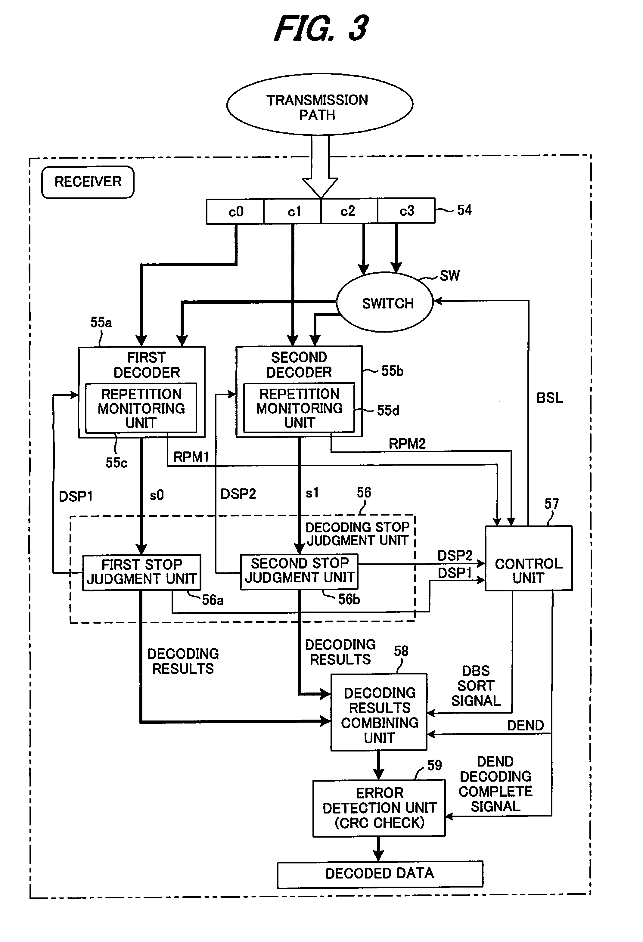
[0065]FIG. 3 is a block diagram of the main parts of a receiving device of a first embodiment of the present invention, where the same reference numbers are used for parts that are the same as those shown in FIG. 1. The same is true for all of the embodiments, but in the first embodiment shown in FIG. 3, the receiving unit, demodulation unit and separation unit are omitted from the figure, however the construction is the same as that shown in FIG. 1

[0066]After likelihood data for code blocks c0 to c3 has been saved in a buffer 54, first and second decoders 55a, 55b fetch the likelihood data of two code blocks c0, c1 in order from the start, and simultaneously execute the decoding process. The maximum number of repetitions of the decoding process by the first and second decoders 55a, 55b is specified, for example 8 times respectively and internal repetition monitoring units 55c, 55d monitor whether the number of repetitions has reached 8, and input the monitoring ...

second embodiment

(C) Second Embodiment

[0076]FIG. 6 is a schematic diagram of the main parts of a receiving device of a second embodiment of the invention, where the same reference numbers are used for parts that are the same as those of the receiving device of the first embodiment shown in FIG. 3. The construction of this embodiment differs in that two switches, first and second switches 61a, 61b, are provided for selectively inputting the decoding results of the first and second decoders 55a, 55b to the decoding stop judgment unit 56 and decoding results combining unit 58.

[0077]When the conditions for stopping decoding have been met for all of the code blocks except for one remaining code block, the control unit 57 controls the switches 61a, 61b and inputs the decoding results of the last code block to the decoding results combining unit 58. After the decoding process for the final block, the decoding results combining unit 58 serially combines the decoding result of the final block with the decodi...

third embodiment

(D) Third Embodiment

[0085]FIG. 8 is a schematic diagram of the main parts of a receiving device of a third embodiment of the invention, where the same reference numbers are used for parts that are the same as those of the receiving device of the first embodiment shown in FIG. 3. The construction of this embodiment differs in that two switches, first and second switches 61a, 61b, are provided that selectively input the decoding results from the first and second decoders 55a, 55b to the decoding stop judgment unit 56 and decoding results combining unit 58.

[0086]FIG. 9 is a flowchart of the processing by a control unit 57 of this third embodiment.

[0087]The control unit 57 monitors whether decoding stop signals DSP1, DSP2 have been generated (step 201), and when they are not generated, makes reference to the monitoring results RPM1, RPM2 to check whether the number of times decoding has been performed by the first and second decoders 55a, 55b has reached the maximum number of repetition...


PUM


Abstract

A receiving device in a communication system that separates one frame of information bits into plural blocks, performs turbo encoding of the information bits of each block and transmits the result, and decodes the encoded information bits, where the receiving device includes plural decoders number of which is less than the number of blocks per frame. Each decoder performs a decoding process on encoded information bits of each block that have been expressed by likelihood, when a condition for stopping decoding is met, executes the decoding process of encoded information bits of another block for which decoding has not yet been performed. When the condition for stopping decoding has been met for all block before the number of times decoding has been performed for each decoder reaches a preset maximum number of repetitions, the decoding results of all the blocks are serially combined, an error detection process is executed, and when no error is detected, the decoding results are output.

Description

CROSS-REFERENCE TO RELATED APPLICATION[0001]This application is a continuation application of international PCT application No. PCT / JP2006 / 315287 filed on Aug. 2, 2006.BACKGROUND OF THE INVENTION[0002]The present invention relates to a receiving device and the decoding method thereof, and may be related to a receiving device and the decoding method thereof in a communication system in which a transmitter separates the information bits of one frame into plural code blocks, encodes the information bits of each code block using code that reduces errors in the decoding results each time decoding process is repeated and transmits the results, and the receiving device receives the encoded information bits of each code block, and decodes the encoded information bits to the information bits before encoding.[0003]In a communication system, a transmitter performs an encoding process on transmission data, then transmits the obtained encoded data via a transmission path, and a receiver performs...

Claims


Application Information

Patent Timeline
Patent Type & Authority Applications(United States)
IPC IPC(8): H03M13/05G06F11/10H03M13/45
CPCH03M13/2975H03M13/2978H04L1/0066H04L1/005H04L1/0052H03M13/6561H03M13/29
Inventor MIYAZAKI, SHUNJIOBUCHI, KAZUHISAIKEDA, NORIHIRO
Owner FUJITSU LTD
Why Eureka
Try Eureka