Passive circuit for improved differential amplifier common mode rejection

a technology of differential amplifier and common mode rejection, which is applied in the field of electric circuits, can solve the problem of sufficiently high impedance of the industry

Inactive Publication Date: 2009-05-21
TEXAS INSTR INC
View PDF14 Cites 9 Cited by
  • Summary
  • Abstract
  • Description
  • Claims
  • Application Information

AI Technical Summary

Benefits of technology

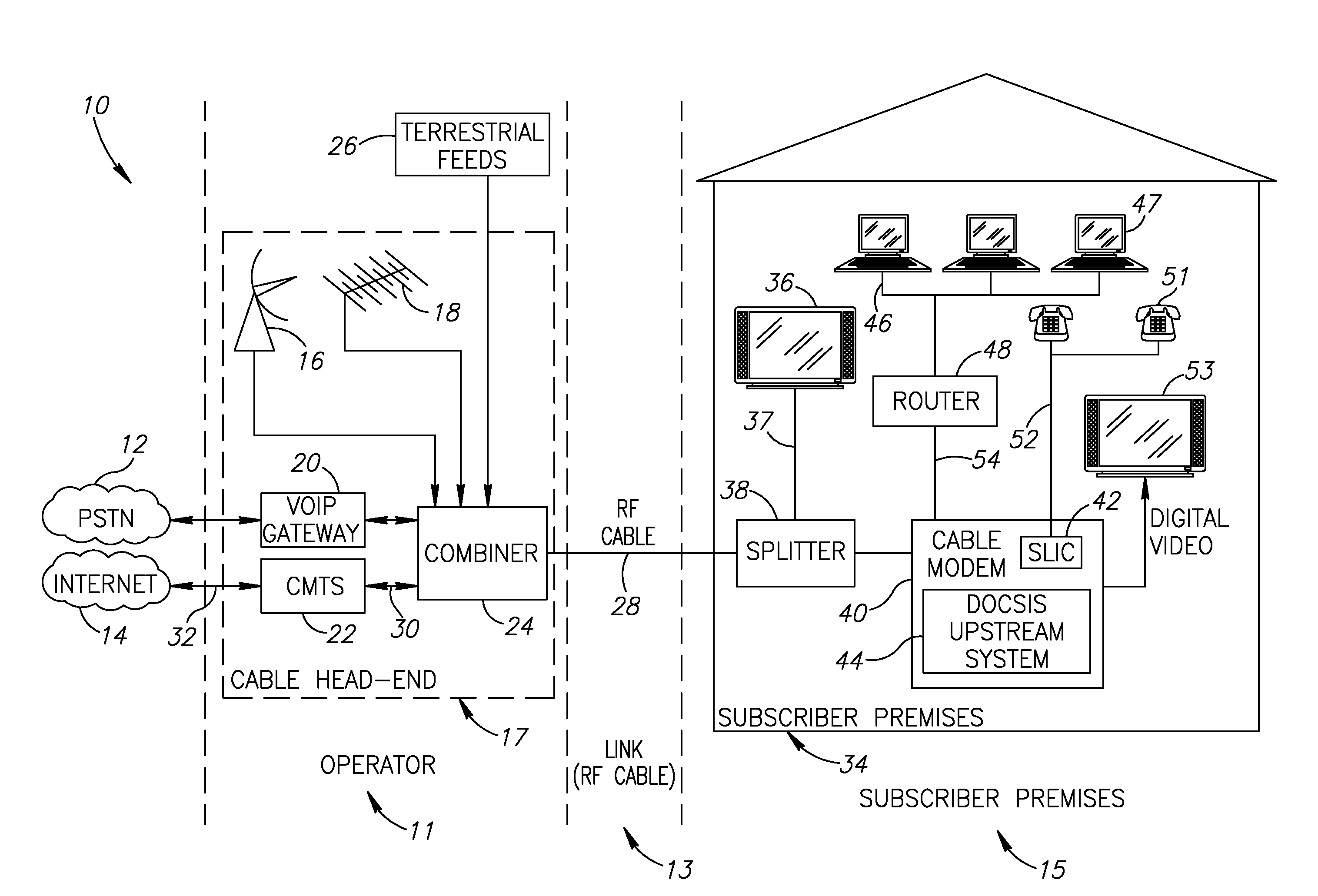
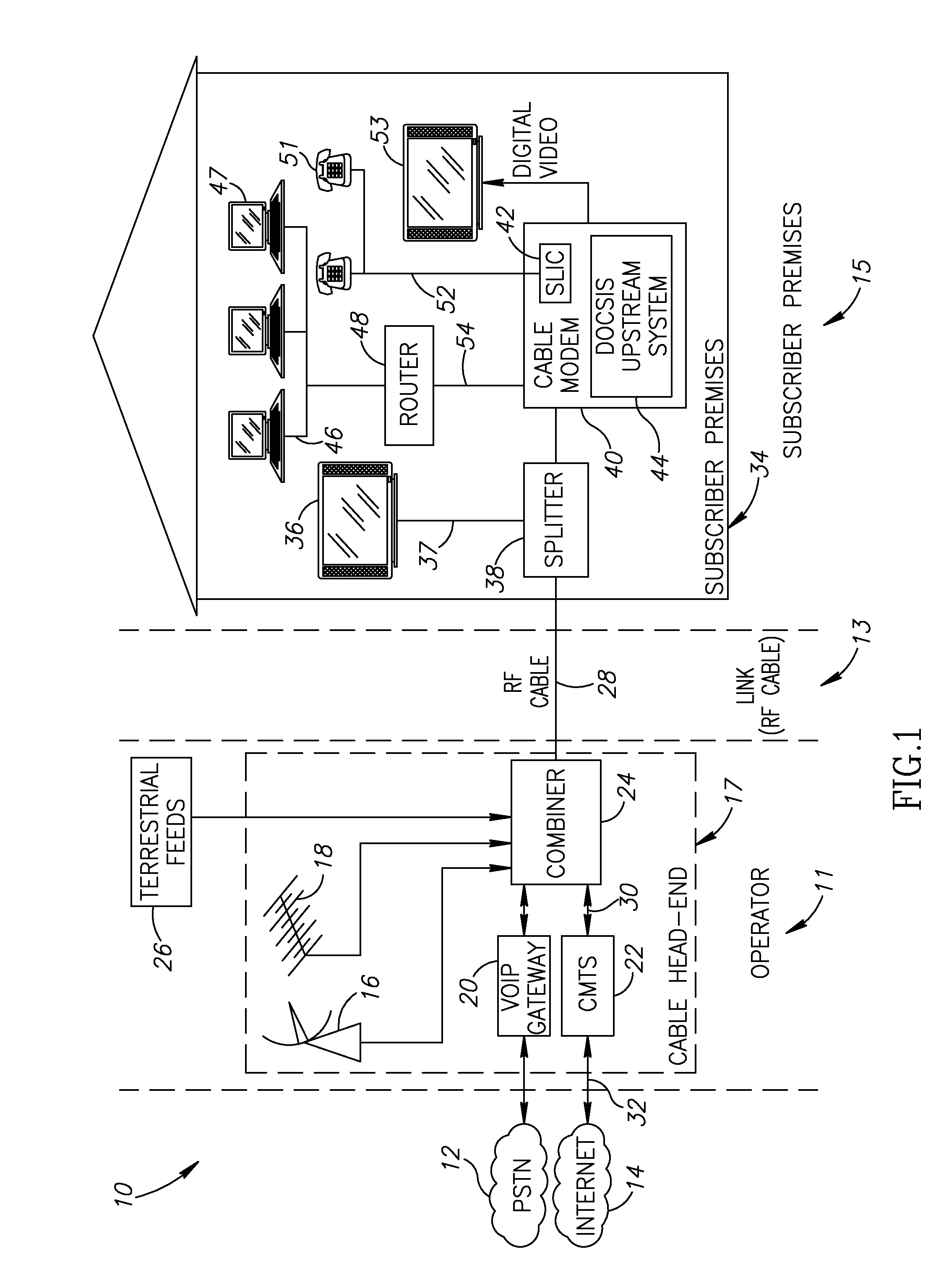
[0010]Several advantages of the amplitude mismatch compensation circuit of the present invention include (1) the common mode rejection of spurious frequency products is significantly improved using a relatively simple passive circuit comprising a few passive components; (2) the cost of the several passive components is extremely low; and (3) implementation of the invention in existing circuit designs does not require extensive and expensive redesign.
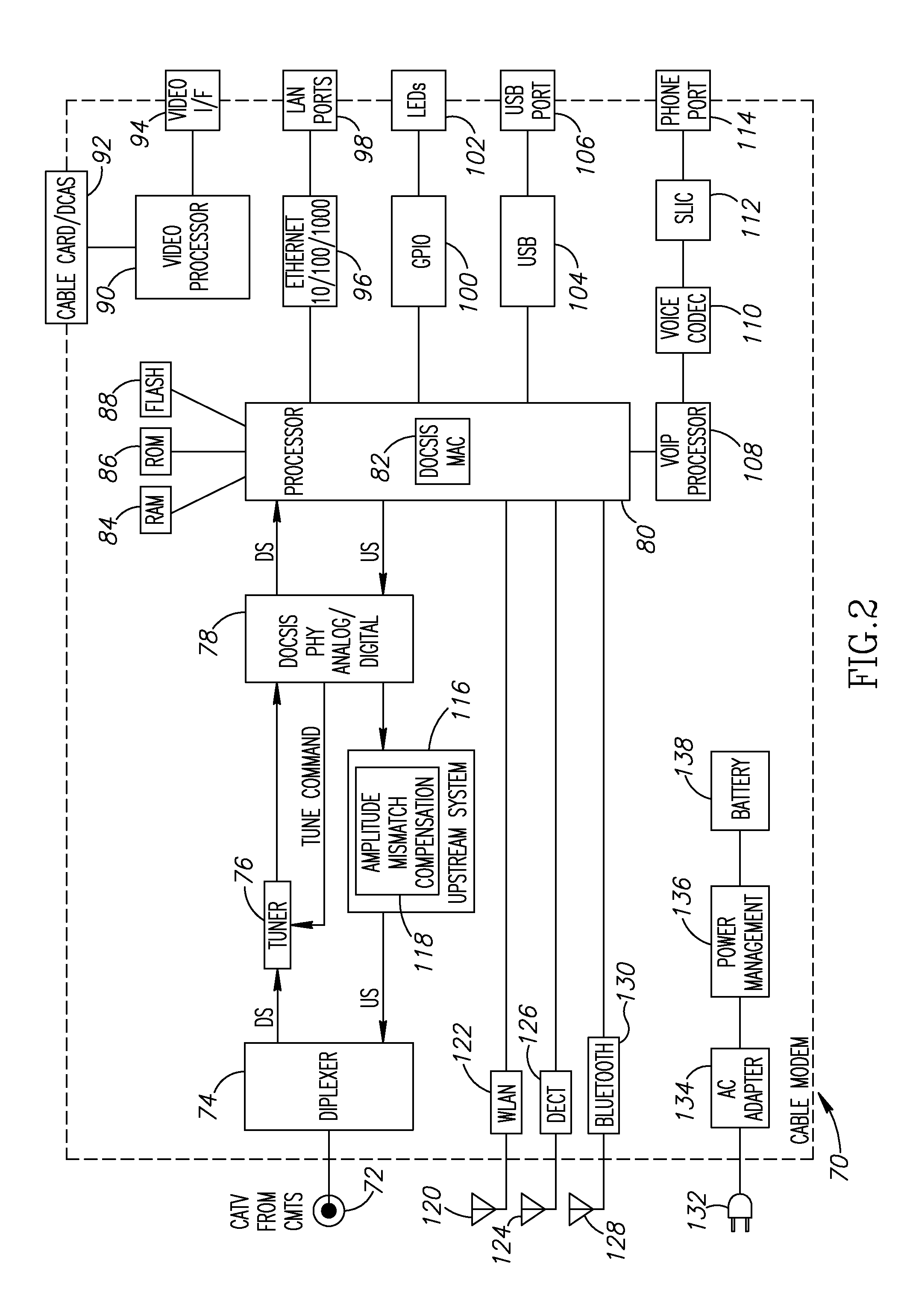
[0013]There is also provided in accordance with the invention, a circuit comprising a differential amplifier operative to generate a differential output comprising a first output and a second output, a first parallel R-L circuit connected in series with the first output, a second parallel R-L circuit connected in series with the second output and wherein the first R-L circuit and the second R-L circuit are operative to substantially compensate for any amplifier mismatch between the first output and the second output.

Problems solved by technology

At high frequencies, however, the inductor impedance is sufficiently high that the series resistor compensates for the imbalance caused by spurious products (i.e. noise or interference sources).

Method used


Image

  • Passive circuit for improved differential amplifier common mode rejection
  • Passive circuit for improved differential amplifier common mode rejection
  • Passive circuit for improved differential amplifier common mode rejection

Examples


Embodiment Construction

Notation Used Throughout

[0030]The following notation is used throughout this document.

TermDefinitionACAlternating CurrentADCAnalog to Digital ConverterASICApplication Specific Integrated CircuitATMAsynchronous Transfer ModeCATVCommunity Antenna Television or Cable TVCMCable ModemCMRCommon Mode RejectionCMRRCommon Mode Rejection RatioCMTSCable Modem Termination SystemCOCentral OfficeCPUCentral Processing UnitDACDigital to Analog ConverterDCDirect CurrentDCASDownloadable Conditional Access SystemsDECTDigital Enhanced Cordless TelecommunicationsDHCPDynamic Host Control ProtocolDOCSISData Over Cable Service Interface SpecificationDSDownstreamDSLDigital Subscriber LineDSPDigital Signal ProcessorDVRDigital Video RecorderEEROMElectrically Erasable Read Only MemoryFPGAField Programmable Gate ArrayGPIOGeneral Purpose I / OHDLHardware Description LanguageI / FInterfaceI / OInput / OutputICIntegrated CircuitIPInternet ProtocolIRFImage Reject FilterLANLocal Area NetworkLEDLight Emitting DiodeLPFLow Pas...


PUM


Abstract

A novel passive circuit for providing improved common mode rejection of a differential amplifier novel. The passive circuit functions to compensate for amplitude mismatches between the two outputs of a differential amplifier. To compensate for the amplitude mismatch between the output traces of the amplifier, a resistor is inserted in series with at either one or both of the differential outputs. The values of the resistors are set such that the mismatch is substantially eliminated. Inductors are connected in parallel with the resistors to create a zero ohm path for power. At high frequencies the inductor impedance is sufficiently high that the series resistor compensates for the imbalance caused by spurious products. The imbalance in the amplifier outputs is corrected with the resulting increase in the rejection of spurious frequency products by exploiting the differential common mode rejection (CMR) effect of the differential amplifier.

Description

FIELD OF THE INVENTION[0001]The present invention relates to the field of electrical circuits and more particularly relates to a passive circuit for providing improved common mode rejection of a differential amplifier.BACKGROUND OF THE INVENTION[0002]Differential amplifiers are well known in the electrical art. A differential amplifier is a type of electronic amplifier that multiplies the difference between two inputs by some constant factor (i.e. the differential gain). A differential amplifier is normally used as the input stage of operational amplifiers (i.e. op amps) and emitter coupled logic gates. The common mode rejection ratio (CMRR) of a differential amplifier measures the tendency of the device to reject input signals common to both input leads. A high CMRR is important in applications where the signal of interest is represented by a small voltage fluctuation superimposed on a voltage offset (which may be rather large) or when relevant information is contained in the volta...

Claims


Application Information

Patent Timeline
Patent Type & Authority Applications(United States)
IPC IPC(8): H04N7/173
CPCH03F3/45085H03F3/45618H03F2203/45731H03F2203/45638H03F2203/45702H03F2200/09
Inventor KLEIN, SHAULBEN-HAMO, ORENMEIR, MOSHEEZRA, RONEN
Owner TEXAS INSTR INC
Why Eureka
Try Eureka