Aircraft wing and flap deployment system

Active Publication Date: 2009-05-28
AIRBUS OPERATIONS LTD
View PDF11 Cites 49 Cited by
  • Summary
  • Abstract
  • Description
  • Claims
  • Application Information

AI Technical Summary

Benefits of technology

[0010]By decreasing the degree of sweep of the trailing edge of the aircraft, the flap can increase the aerodynamic and/or structural efficiency of the wing and maximize lift.
[0011]The trailing edge of the wing may be swept forward, and in this case the flap locally reduces the fo

Problems solved by technology

A degree of sweep in the trailing edge of the wing may be desirable to reduce drag during high speed operat

Method used


Image

  • Aircraft wing and flap deployment system
  • Aircraft wing and flap deployment system
  • Aircraft wing and flap deployment system

Examples


Embodiment Construction

)

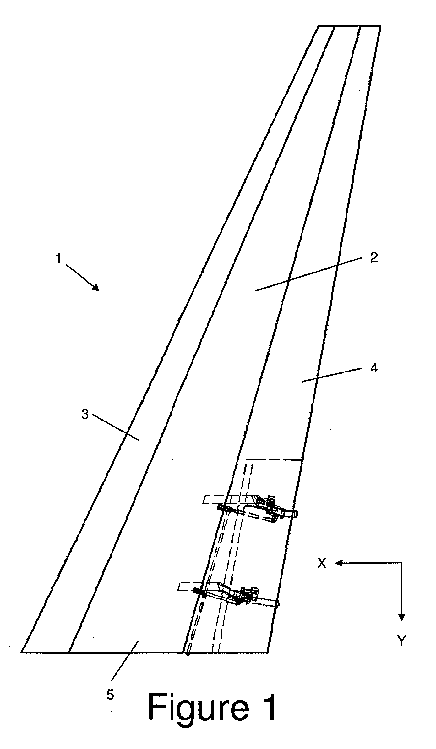
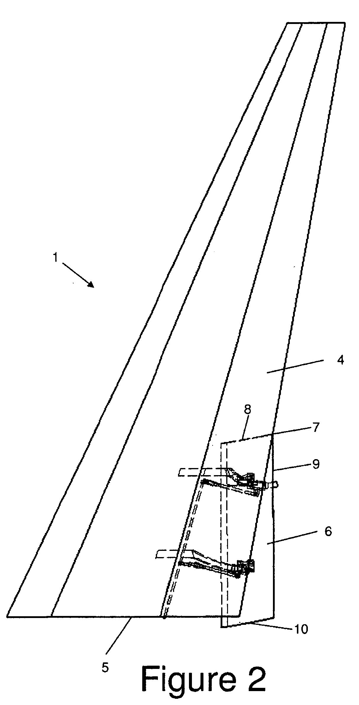
[0033]An aircraft wing 1 shown in FIGS. 1-3 comprises a wing box 2; a leading edge upper panel 3; and a trailing edge upper panel 4. The wing box has an inboard end 5 (conventionally known as a wing root) connected to a fuselage (not shown).

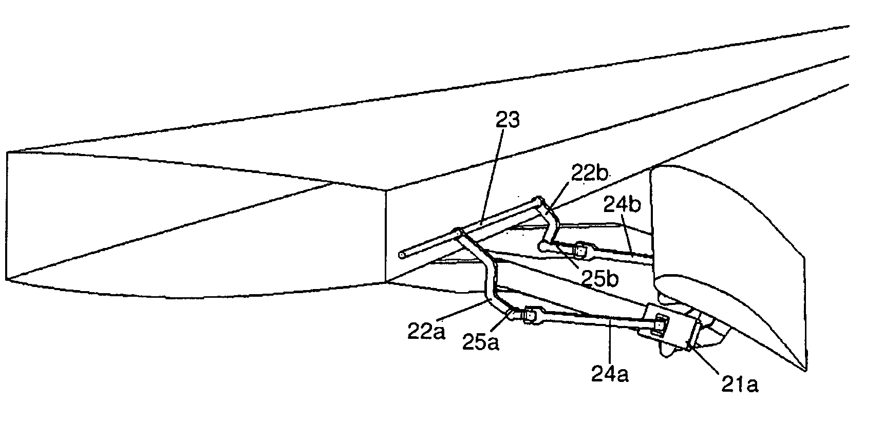
[0034]The wing box 2 carries a number of high lift devices including slats on its leading edge and flaps on its trailing edge. The most inboard flap 6 of the wing, known as a Yehudi flap, is illustrated in FIGS. 1-3 in its retracted, intermediate and fully deployed positions respectively.

[0035]The movement of the flap 6 includes a component of horizontal rotation about a vertical axis passing through the point 7 (labelled in FIG. 2) where the outboard edge 8 of the flap 6 meets its leading edge 9. Thus as the flap is deployed, its inboard edge 10 moves along a longer path than its outboard edge 8 when viewed in plan, as can be seen by a comparison of FIGS. 2 and 3 with FIG. 1.

[0036]As shown in FIG. 4, the wing box 2 comprises upper and lower ski...


PUM


Abstract

An aircraft wing comprising: a main wing element; and a flap connected to the main wing element by a deployment system which can deploy the flap from a retracted position to an extended position, wherein the wing has a trailing edge which is swept, at least in the region of the flap, when the flap is in its retracted position, and wherein the deployment system is arranged such that the flap reduces the degree of sweep of the trailing edge of the wing in the region of the flap as it is deployed. The deployment system comprises a first actuator configured to rotate the flap horizontally so as to change the sweep angle of the flap and a second actuator configured to rotate the flap vertically so as to increase the camber of the wing, and the first and second actuators are operable independently of each other.

Description

FIELD OF THE INVENTION[0001]The present invention relates to an aircraft wing comprising: a main wing element; and a flap connected to the main wing element by a deployment system which can deploy the flap from a retracted position to an extended position. The invention also relates to a method and system for deploying the flap.BACKGROUND OF THE INVENTION[0002]Conventional flap deployment systems include flap track mechanisms, drop link mechanisms, and multi-bar linkage mechanisms. Flap track mechanisms employ a track on which the flap runs on roller bearings as it moves between its retracted and extended positions. Drop link mechanisms employ a rigid drop link which is pivotally coupled at one end to the main wing element and to the flap at the other end.[0003]Most flap deployment systems impart a vertical rotation to the flap so as to increase the camber of the wing. Some also impart a degree of rearward translation to the flap (commonly referred to as “Fowler motion”). US 2007 / 00...

Claims


Application Information

Patent Timeline
IPC IPC(8): B64C3/50B64C3/10
CPCB64C9/16Y02T50/44Y02T50/32Y02T50/30Y02T50/40
Inventor ENGELBRECHT, THOMAS H.THOMPSON, ROBERT I.WHITE, NICHOLAS J.
Owner AIRBUS OPERATIONS LTD
Why Eureka
Try Eureka