Magnetic resonance imaging system and RF coil

a magnetic resonance imaging and radio frequency coil technology, applied in the field of magnetic resonance imaging systems and radio frequency coils, can solve the problem that heat generation cannot be efficiently suppressed, and achieve the effect of dissipating heat generated and dissipating heat generated

Active Publication Date: 2009-05-28
TOSHIBA MEDICAL SYST CORP
View PDF16 Cites 86 Cited by
  • Summary
  • Abstract
  • Description
  • Claims
  • Application Information

AI Technical Summary

Benefits of technology

[0009]According to one aspect of the present invention, a magnetic resonance imaging system includes a Radio Frequency (RE) coil that applies a high-frequency magnetic field to a subject placed in a static magnetic field, wherein the RF coil includes a plurality of conductive members; and circuit elements connected to the conductive members, and each of the conductive members is at least partially formed so as to meet at least any one of conditions of a thickness, a shape, and a material that are capable of dissipating heat generated from the circuit elements.
[001...

Problems solved by technology

However, heat is locally generated due to heat generation by various circuit elements around an RE coil, so that sometimes heat g...

Method used


Image

  • Magnetic resonance imaging system and RF coil
  • Magnetic resonance imaging system and RF coil
  • Magnetic resonance imaging system and RF coil

Examples


Embodiment Construction

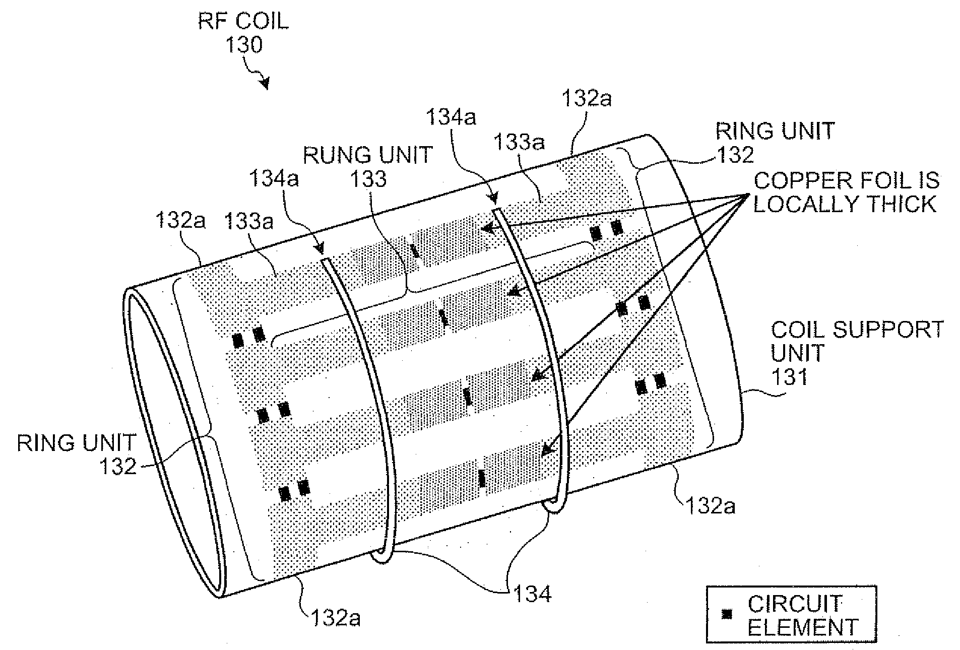
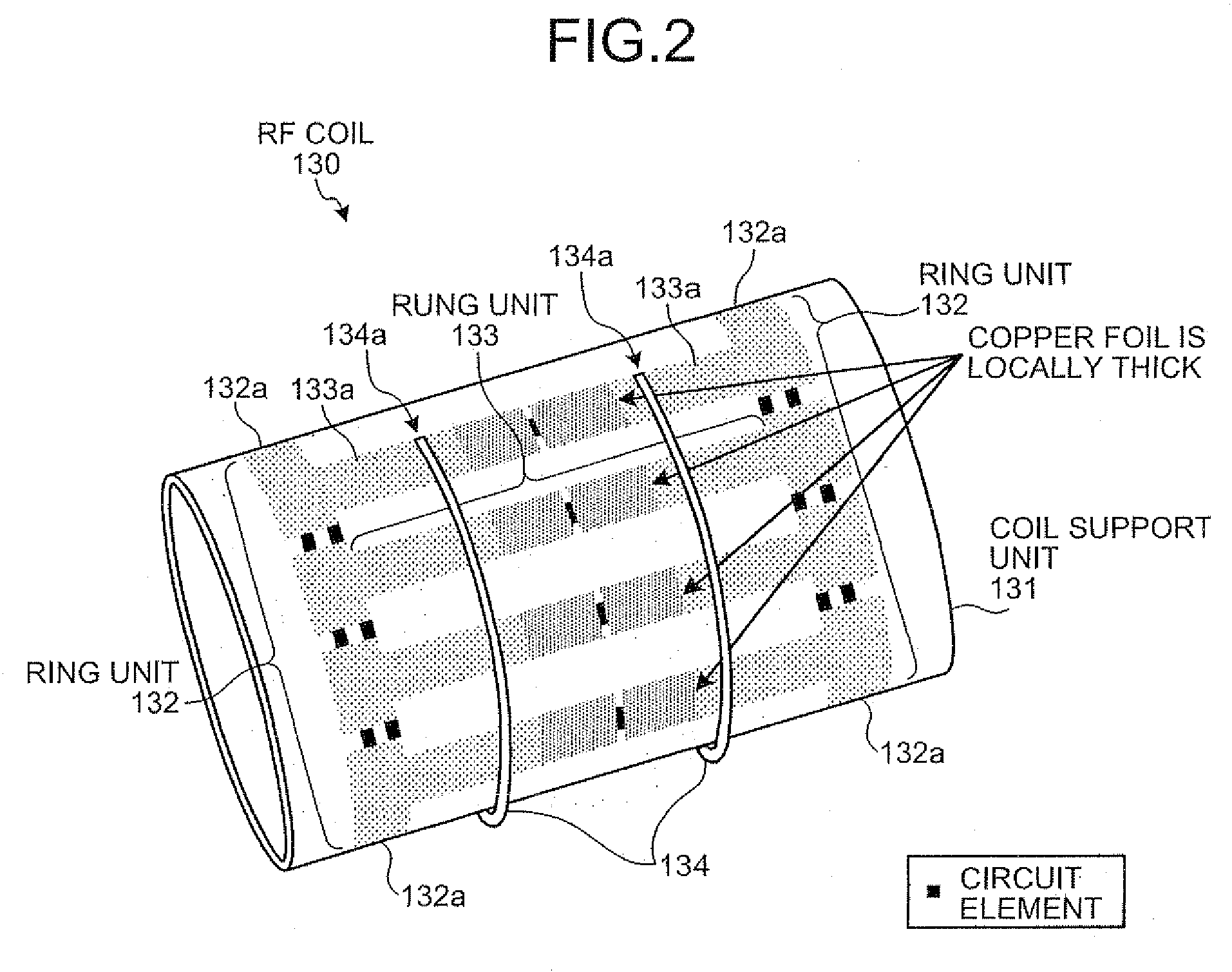
[0018]Exemplary embodiments of a magnetic resonance imaging system and a Radio Frequency (RF) coil of the present invention will be explained below in detail with reference to the accompanying drawings. Hereinafter, a Magnetic Resonance Imaging system is referred to as an MRI system.

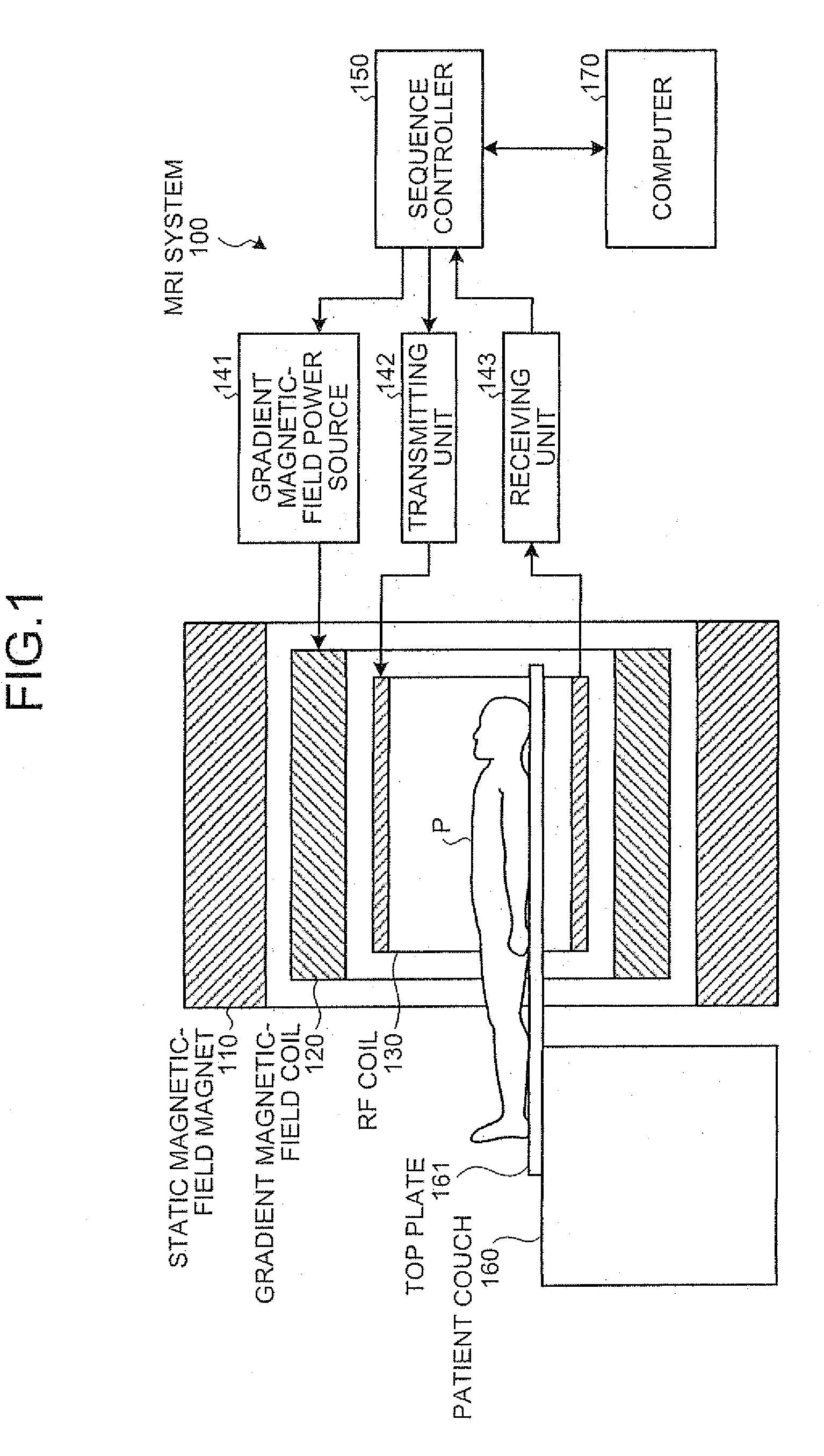
[0019]First of all, a general configuration of an MRI system 100 according to an embodiment of the present invention is explained below. FIG. 1 is a schematic diagram for explaining a general configuration of the MRI system 100 according to the embodiment. As shown in FIG. 1, the MRI system 100 includes a static magnetic-field magnet 110, a gradient magnetic-field coil 120, an RF coil 130, a gradient magnetic-field power source 141, a transmitting unit 142, a receiving unit 143, a sequence controller 150, a patient couch 160, and a computer 170.

[0020]The static magnetic-field magnet 110 is a magnet formed in a cylindrical shape, and generates a static magnetic field in a space inside a barrel in which a ...


PUM


Abstract

When an RF coil in a magnetic resonance imaging system includes a plurality of conductive members and circuit elements connected to the conductive members, at least part of each of the conductive members is formed to a thickness so as to dissipate heat generated from the circuit elements. Moreover, the magnetic resonance imaging system is configured to include a cooling unit that circulates cooling air over the surfaces of the circuit elements provided in the RF coil.

Description

CROSS-REFERENCE TO RELATED APPLICATIONS[0001]This application is based upon and claims the benefit of priority from the prior Japanese Patent Application No. 2007-303003, filed on Nov. 22, 2007, and No. 2008-272463, filed on Oct. 22; the entire contents of which are incorporated herein by reference.BACKGROUND OF THE INVENTION[0002]1. Field of the Invention[0003]The present invention relates to a magnetic resonance imaging system and a Radio Frequency (RF) coil. Particularly, the present invention relates to a magnetic resonance imaging system and an RF coil that can suppress heat generated around the RF coil.[0004]2. Description of the Related Art[0005]A magnetic resonance imaging system applies a high-frequency magnetic field over a subject placed in a static magnetic field, detects a nuclear magnetic resonance signal emitted from the subject with the high-frequency magnetic field, and reconstructs an image. Such magnetic resonance imaging system includes an RF coil that applies th...

Claims


Application Information

Patent Timeline
IPC IPC(8): G01R33/32
CPCG01R33/34046G01R33/28G01R33/34076
Inventor TOMIHA, SADANORIISHIHARA, TAKAHIROMITSUI, SHINJITAKAMORI, HIROMITSUKATSUNUMA, AYUMI
Owner TOSHIBA MEDICAL SYST CORP
Why Eureka
Try Eureka