Antenna arrangement with interleaved antenna elements

an antenna element and interleaved technology, applied in the direction of polarised antenna unit combinations, individually energised antenna arrays, resonant antennas, etc., can solve the problems of consuming space, affecting the performance of the antenna, so as to reduce the coupling and minimize the space needed

Active Publication Date: 2009-05-28
INTEL CORP
View PDF10 Cites 165 Cited by
  • Summary
  • Abstract
  • Description
  • Claims
  • Application Information

AI Technical Summary

Benefits of technology

[0009]An object with the present invention is to provide a multiple frequency-band antenna arrangement, and an antenna system, that will reduce the coupling between different frequency bands while at the same time minimizing the space needed compared to prior art antennas.

Problems solved by technology

However, this requires enough space to implement and the arrangement may also be sensitive to interference between the RF signals in the different frequency bands.
A drawback with this prior art embodiment is that the frequency bands FB1 and FB2 will couple to each other due to the closeness of the parts making up the antenna element 11.
If the frequency bands are too close, filters with high Q values, for example cavity filters which consume space and are relatively expensive and heavy, must be used very close to the antenna elements.

Method used


Image

  • Antenna arrangement with interleaved antenna elements
  • Antenna arrangement with interleaved antenna elements
  • Antenna arrangement with interleaved antenna elements

Examples


second embodiment

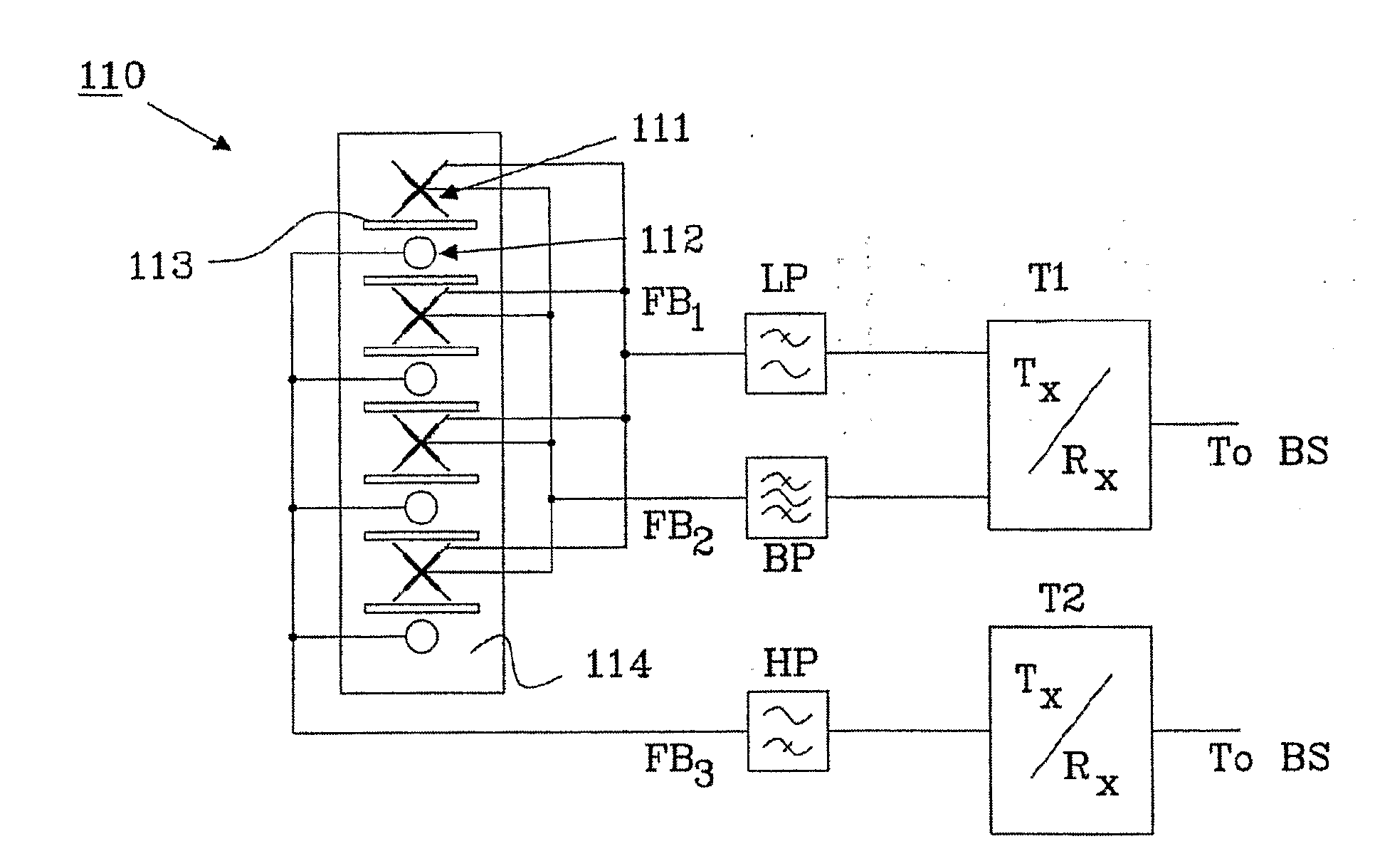
[0041]In FIG. 4, a perspective view of a dual band antenna array 40 is shown. The dual band antenna array 40 contains two types of antenna elements, a first type 41 for the lower frequency band and a second type 42 for the higher frequency band. As an example, the first type of antenna elements 41 only receives RF signals within a range of 1920-1980 MHz and the second type of antenna elements 42 only transmits RF signals within a range of 2110-2170 MHz, which leaves a suppressed frequency band of 130 MHz therebetween. Thereby a traditional antenna for the UMTS band is replaced by a dual band antenna with separate antenna elements for the RX band and Tx band, respectively, so that simplified Tx and Rx radio chains can be realized.

[0042]Both types 41 and 42 of antenna elements are made of a DRA (Dielectric Resonator Antenna) which are considerable smaller than conventional patch antennas. The drawback with the DRA is that they might have a narrow bandwidth compared to other types of a...

third embodiment

[0043]In FIG. 5, a perspective view of a dual band antenna array 50 is shown. The dual band antenna array 50 contains two types of antenna elements, a first type 51 for the lower frequency band and a second type 52 for the higher frequency band. As an example, the first type of antenna elements 51 transmits and receives RF signals within a range of 1710-2170 MHz, which is similar to the antenna element 31 described in connection with FIG. 3. The second type of antenna elements 52 transmits and receives RF signals within a range of 2.5-2.7 GHz, which is the same frequency band as antenna element 32 (FIG. 3) operated within.

[0044]A difference between the previously described antenna element 32 and the antenna element 52 is the type of antenna element being used. In the third embodiment described in connection with FIG. 5, a DRA is used as the second type of antenna element. Although the DRA might have a narrow bandwidth, the second antenna element will be sufficient to ensure proper o...


PUM


Abstract

The present invention relates to an antenna arrangement connectable to a transceiver for transmitting and receiving RF signals in at least two separate frequency bands. The antenna arrangement has at least two sets of antenna elements arranged on a reflector, and the antenna elements are arranged in an interleaved configuration along a single column. The two separate frequency bands are substantially non-overlapping but relatively close to each other, and the distance between adjacent antenna elements in said column is substantially the same along the column.

Description

TECHNICAL FIELD[0001]The present invention relates to an antenna arrangement with interleaved antenna elements for multiple frequency band operation, especially for mobile communication systems, as defined in the preamble of claim 1. The invention also relates to an antenna system being adapted to communicate through a communication link with a base station.BACKGROUND TO THE INVENTION[0002]Present antenna arrays used for transmitting and receiving RF (Radio Frequency) signals in mobile communication systems are normally dedicated to a single frequency band or sometimes two or more frequency bands. Single frequency band antennas have been used for a long time and normally include a number of antenna elements arranged in a vertical row. A second row of antenna elements needs to be added beside the first row if the operator in a network wants to add another frequency band using single frequency band antennas. However, this requires enough space to implement and the arrangement may also...

Claims


Application Information

Patent Timeline
Patent Type & Authority Applications(United States)
IPC IPC(8): H01Q21/00H01Q1/52H01Q1/50H01Q5/42
CPCH01Q1/523H01Q5/00H01Q9/04H01Q5/42H01Q21/08H01Q21/26H01Q21/28H01Q15/166H01Q1/526H01Q19/104H01Q21/10H01Q21/30H01Q1/2216H01Q1/246
Inventor LINDMARK, BJORNUDDIN, JESPER
Owner INTEL CORP
Why Eureka
Try Eureka