Method for Driving Liquid Crystal Display Apparatus

a liquid crystal display and display technology, applied in the field of methods for driving liquid crystal display apparatuses, can solve the problems of long completion time, low response speed of liquid crystal display apparatus, etc., and achieve the effect of preventing deterioration in display quality and increasing response speed

Inactive Publication Date: 2009-05-28
SHARP KK
View PDF25 Cites 22 Cited by
  • Summary
  • Abstract
  • Description
  • Claims
  • Application Information

AI Technical Summary

Benefits of technology

[0017]According to the foregoing invention, the applied voltages respectively corresponding to the gradations of less than the predetermined gradations m (1≦m≦(n−2)) are not used when a moving image is displayed. As a result, a low-gradation display is not carried out in a normally black system. This causes a range of luminances that can be displayed to be narrower than when normal display driving is performed, thereby causing deterioration in display quality.
[0018]In view of this, the present invention overlaps (n−m) types of gradation partially so that n gradations are obtained and then sorts the n gradations into a range of (i) an applied voltage corresponding to the predetermined gradation m to (ii) an applied voltage corresponding to the gradation (n−1). Therefore, even when the applied voltages respectively corresponding to the gradations of less than the predetermined gradation m are not used, the n gradations can be expressed. This makes it possible to prevent deterioration in display quality. Further, since the overdrive driving is performed, the response speed is increased.

Problems solved by technology

Conventionally, a liquid crystal display apparatus has had a problem of low response speed.
Moreover, the low response speed of the liquid crystal display apparatus is attributed to the fact that it takes a long time to complete the change caused in orientation state of the liquid crystal molecules in response to the change in voltage applied to the liquid crystal layer.
On the other hand, high-quality picture technologies often cause a decrease in response speed simultaneously (e.g., AVS and mobile AVS).
However, as shown in FIG. 9, such a method causes deterioration in image quality.
However, a change in overdrive amount only causes a change in size of the left angular portion, and does not result in an improvement in the right sloping portion.
Therefore, there is no improvement in display.
Further, as described above, an excessive overdrive amount causes a strikingly white display to be produced at the angular portion, thereby causing deterioration in display quality.
Furthermore, even when the overdrive driving is performed, a sufficient speed may not be able to be obtained in a low-gradation region due to the aforementioned low response speed.
That is, the aforementioned low response speed of a liquid crystal display apparatus is not seen uniformly all over the gradation-level regions, but is such that the response speed becomes extremely low in part of the gradation regions.
Further, the response speed of a normally white liquid crystal display apparatus (mobile ASV) is extremely low in a transition from a high gradation (white display) to an intermediate gradation.
These low response speeds cause display problems such as residual images.

Method used


Image

  • Method for Driving Liquid Crystal Display Apparatus
  • Method for Driving Liquid Crystal Display Apparatus
  • Method for Driving Liquid Crystal Display Apparatus

Examples


embodiment 1

[0044]An embodiment of the present invention will be described below with reference to FIGS. 1 to 9.

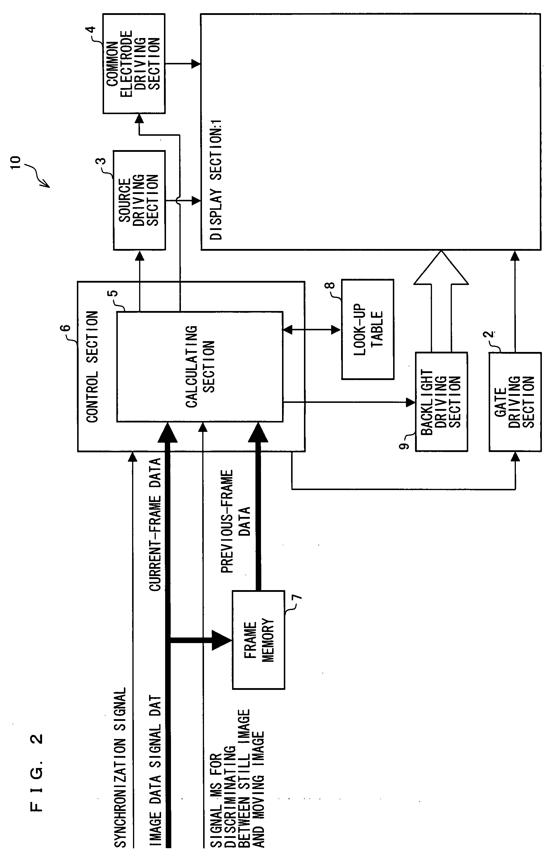
[0045]For example, as shown in FIG. 2, an active matrix liquid crystal display apparatus 10 of the present embodiment includes: a display section 1, a gate driving section 2, a source driving section 3, a common electrode driving section 4, a control section in which a calculating section 5 is provided, a frame memory 7, a look-up table 8, and a backlight driving section 9.

[0046]Although not fully shown in the figure, the display section 1 includes e scanning signal lines that are parallel to one another, f data signal lines that are parallel to one another, and pixels arrayed in a matrix manner. Each of the pixels is formed in a region enclosed by two adjacent scanning signal lines and two adjacent data signal lines.

[0047]The gate driving section 2 sequentially generates, in accordance with a gate clock signal and a gate start pulse each outputted from the control section 6, scanning...

embodiment 2

[0089]Another embodiment of the present embodiment will be described below with reference to FIGS. 10 and 11. Arrangements other than those described in the present embodiment are the same as in Embodiment 1. Further, for convenience of explanation, members having the same functions as those shown in the drawings of Embodiment 1 are given the same reference numerals, and will not be described below.

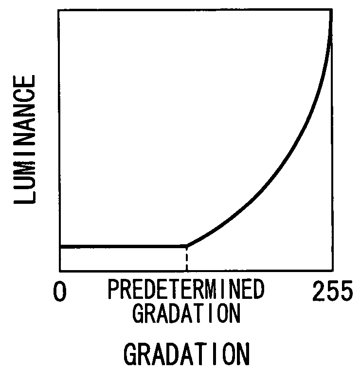
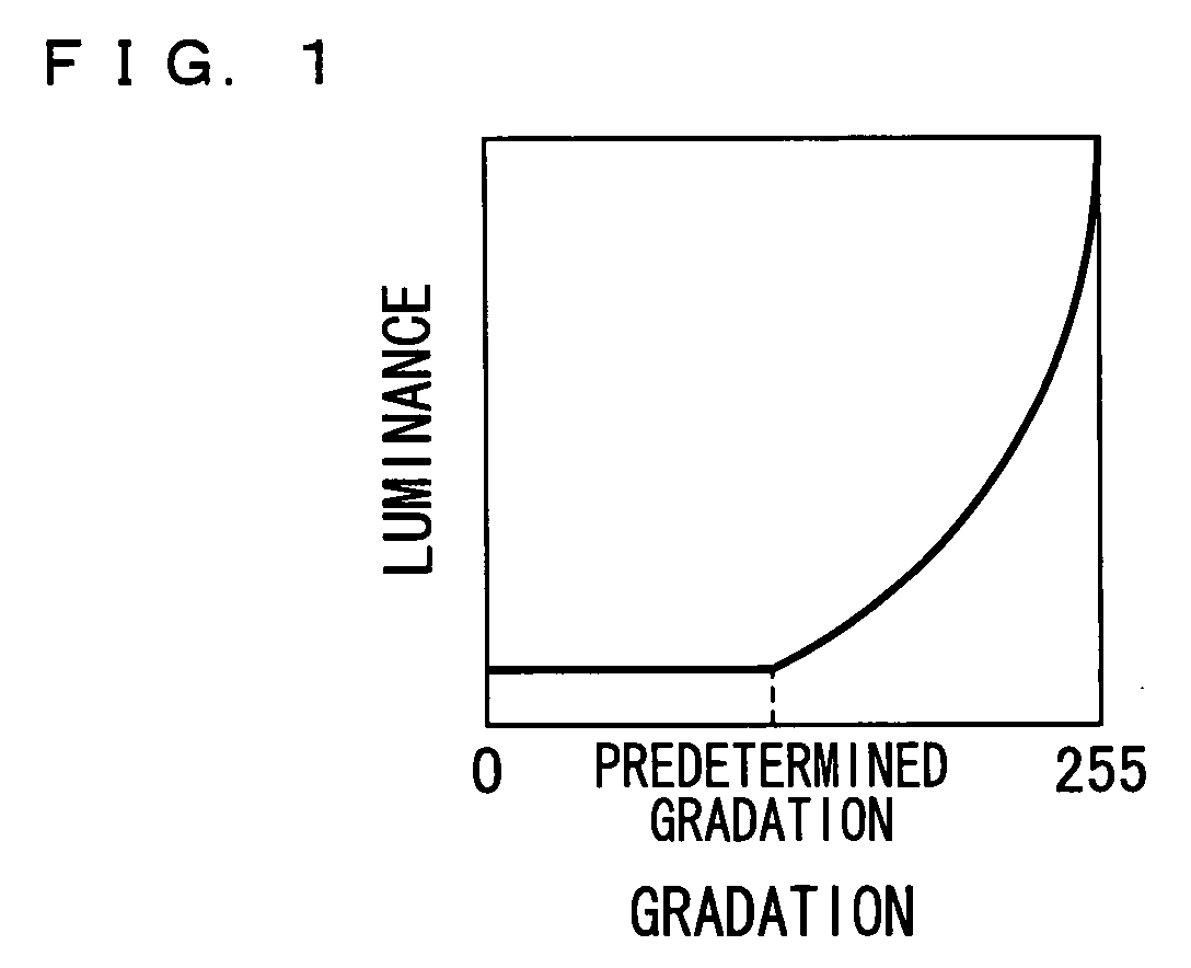
[0090]Embodiment 1 rearranges the gradation range; however, the present invention is not particularly limited to this. As shown in FIG. 10, the applied voltages can be simply shifted. This makes it possible to obtain a wide-range luminance characteristic.

[0091]Incidentally, this method of simply shifting the applied voltages causes an increase in luminance of all the gradations. Therefore, as with Embodiment 1, the y characteristic is changed. As a result, an entirely whitish image is obtained in case of a normally black system, and an entirely dark image is obtained in case of a normally...


PUM


Abstract

In one embodiment of the present invention, when a still image is displayed, applied voltages respectively corresponding to a total of n (n being an integer of not less than 4) types of gradation 0 to (n−1) are outputted to pixels. When a moving image is displayed, an applied voltage corresponding to a predetermined gradation m (1≦m≦(n−2)) is applied to the pixels instead of applied voltages respectively corresponding to gradations of less than the predetermined gradation m. Overdrive driving is performed with respect to a total of n types of gradation.

Description

TECHNICAL FIELD[0001]The present invention relates to methods for driving liquid crystal display apparatuses. Particularly, the present invention relates to a method for driving a liquid crystal display apparatus, which method makes it possible to achieve an improvement in response speed at which a moving image is displayed.BACKGROUND ART[0002]Conventionally, a liquid crystal display apparatus has had a problem of low response speed. That is, a change in display gradation of the liquid crystal display apparatus is such that: a change in orientation state of liquid crystal molecules is made by making a change in voltage applied to a liquid crystal layer, so that the transmittance of a display pixel is changed. Moreover, the low response speed of the liquid crystal display apparatus is attributed to the fact that it takes a long time to complete the change caused in orientation state of the liquid crystal molecules in response to the change in voltage applied to the liquid crystal lay...

Claims


Application Information

Patent Timeline
Patent Type & Authority Applications(United States)
IPC IPC(8): G09G3/36
CPCG09G3/2007G09G3/3696G09G2320/0252G09G2320/0285G09G3/3607G09G2330/021G09G2330/028G09G2340/16G09G2320/103
Inventor YAMATO, ASAHIKAWASHIMA, YUKINAKAGAWA, KIYOSHITAKAHASHI, KOHZOHYANAGI, TOSHIHIRO
Owner SHARP KK
Why Eureka
Try Eureka