
High transmittance touch panel

a touch panel and high transmittance technology, applied in the field of high transmittance touch panel, can solve the problems of non-uniform transmittance, adverse effect of display quality, such as clarity, on the screen of electronic devices, and naked eye view of conductive bodies

Inactive Publication Date: 2009-05-28
ACROSENSE TECH
View PDF13 Cites 90 Cited by
  • Summary
  • Abstract
  • Description
  • Claims
  • Application Information

AI Technical Summary

Benefits of technology

[0006]Therefore, the object of the present invention is to provide a high transmittance touch panel that can eliminate the aforesaid problems with respect to the non-uniform transmittance and clarity of the screen of the electronic device.

Problems solved by technology

Applicant found that when design a touch panel having transparent conductive bodies of a transparent material, such as indium tin oxide (ITO), on a transparent substrate for serving as touch sensors for performing certain functions, there was a clarity problem that the conductive bodies were visible to the naked eye due to a relatively low transmittance or a relatively high reflectance thereof.
Therefore, the touch panel thus formed will be undesirably formed into regions of a higher transmittance (free of the conductive bodies) and regions of a lower transmittance (having the conductive bodies), which will result in a non-uniform transmittance and an adverse effect on the display quality, such as clarity, of the screen of the electronic device.

Method used


Image

  • High transmittance touch panel
  • High transmittance touch panel
  • High transmittance touch panel

Examples


Embodiment Construction

[0017]Before the present invention is described in greater detail with reference to the accompanying preferred embodiments, it should be noted herein that like elements are denoted by the same reference numerals throughout the disclosure.

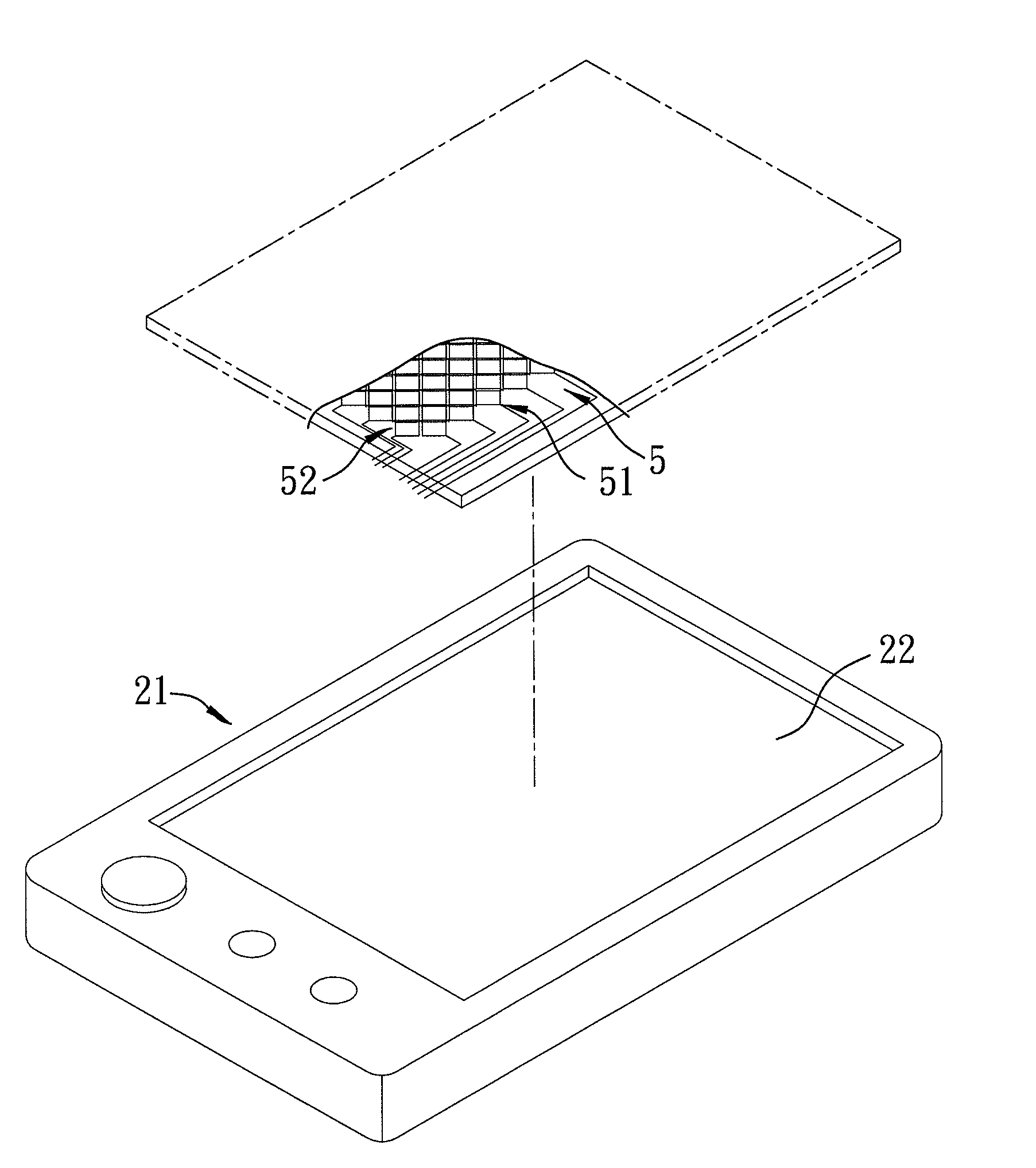
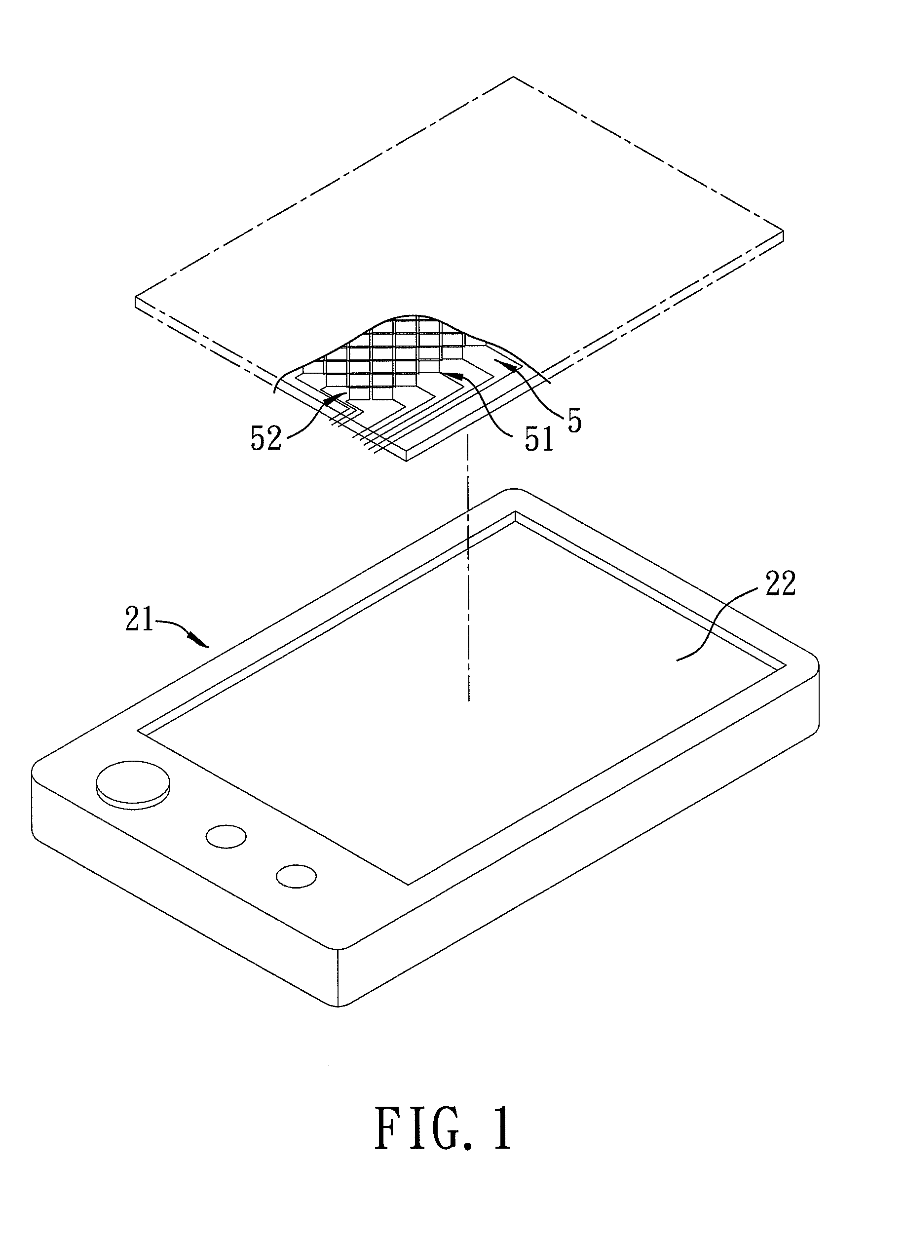
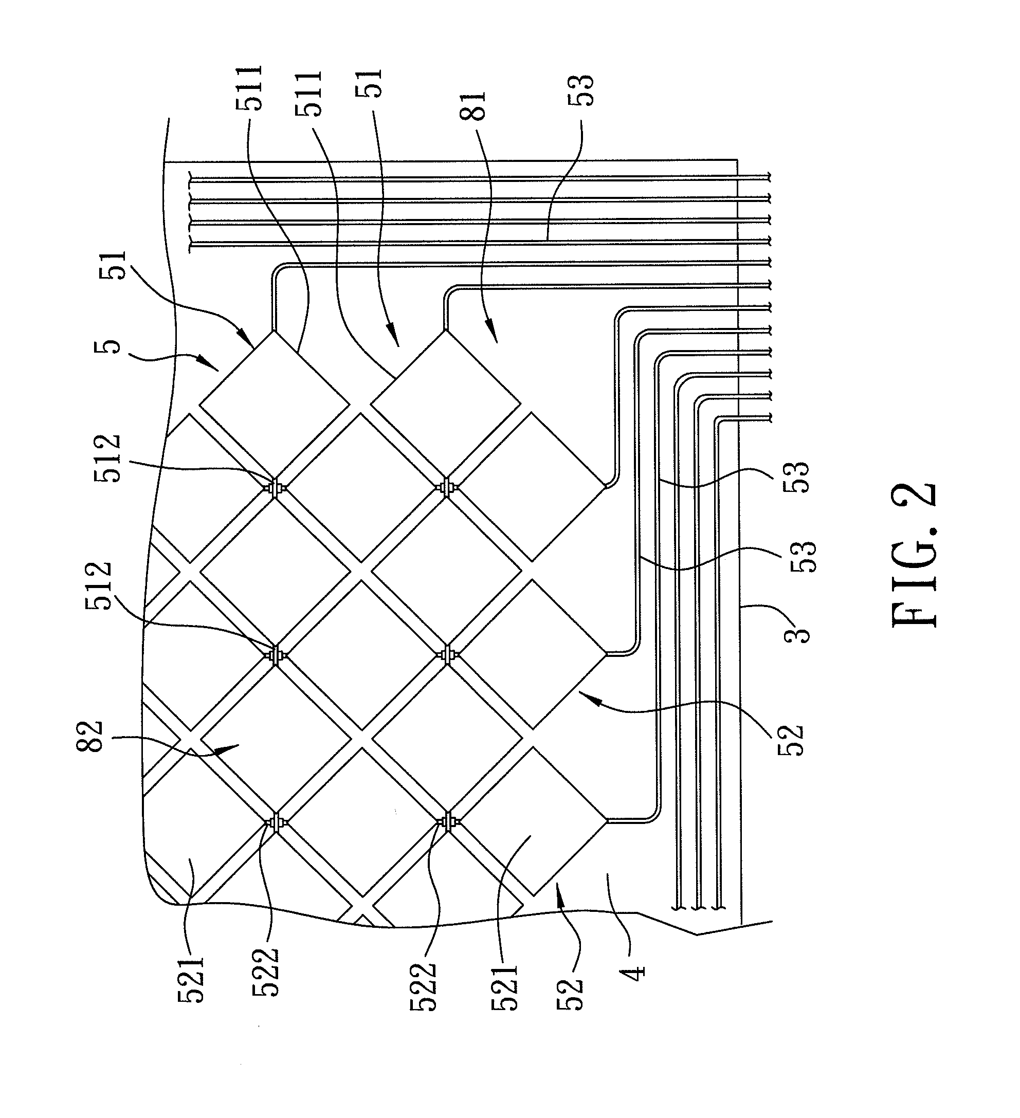
[0018]FIGS. 1 to 3 illustrate the first preferred embodiment of a high transmittance touch panel for mounting on a screen 22 of an electronic device 21 according to this invention. The touch panel includes: a transparent substrate 3; and a transparent multi-layered structure disposed on the substrate 3 and including transparent inner and outer anti-reflection layers 4, 6 and a transparent touch control layer 5 that is sandwiched between the inner and outer anti-reflection layers 4, 6 and that is made from an electrically conductive material. The touch control layer 5 is formed directly on the outer anti-reflection layer 6. The inner anti-reflection layer 4 has a first anti-reflection film 41 formed directly on the touch control layer 5. At least one...


PUM


Abstract

A touch panel includes: a transparent substrate; and a transparent multi-layered structure disposed on the substrate and including transparent inner and outer anti-reflection layers and a transparent touch control layer that is sandwiched between the inner and outer anti-reflection layers and that is made from an electrically conductive material. The inner anti-reflection layer has an anti-reflection film. At least one of the outer anti-reflection layer and the anti-reflection film has an optical thickness sufficient for generating destructive interference among reflections from the substrate, the outer anti-reflection layer, the anti-reflection film, and the touch control layer.

Description

CROSS-REFERENCE TO RELATED APPLICATION[0001]This application claims priority of Taiwanese Application No. 096144535, filed on Nov. 23, 2007.BACKGROUND OF THE INVENTION[0002]1. Field of the Invention[0003]This invention relates to a high transmittance touch panel, more particularly to a high transmittance touch panel including at least one anti-reflection layer having an optical thickness equal to or less than a quarter wavelength of visible light.[0004]2. Description of the Related Art[0005]Touch panels are mounted on a screen of an electronic device and are transparent so as to permit the user to touch icons or command signs shown on the screen to perform desired functions. Applicant found that when design a touch panel having transparent conductive bodies of a transparent material, such as indium tin oxide (ITO), on a transparent substrate for serving as touch sensors for performing certain functions, there was a clarity problem that the conductive bodies were visible to the naked...

Claims


Application Information

Patent Timeline
IPC IPC(8): G06F3/041
CPCG06F3/041G06F3/0412G06F3/0443
Inventor SUN, JENG-HUNG
Owner ACROSENSE TECH
Learn More