
Lens with variable focal length and symmetry

a technology of variable focal length and symmetry, applied in the field of lenses with variable focal length, can solve the problems of image distortion and the risk of clearly insufficient optical opening, and achieve the effect of increasing the thickness of the dielectric and reducing i

Inactive Publication Date: 2009-05-28
EASTMAN KODAK CO
View PDF4 Cites 12 Cited by
  • Summary
  • Abstract
  • Description
  • Claims
  • Application Information

AI Technical Summary

Benefits of technology

[0014]Another object is to free the lens, or an image formed by the lens, from vibrations, movements or accelerations imposed by the recording equipment which is equipped with it.
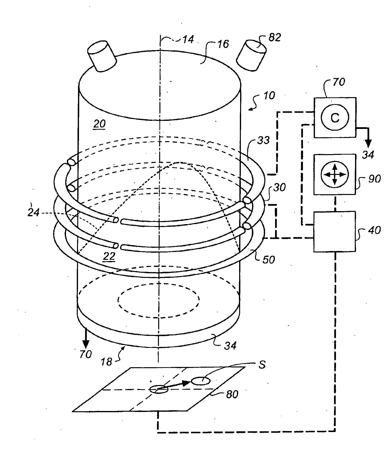
[0031]The off-centering of the annular electrode has the effect of making the distance between the electrode and the liquids variable according to an angle measured around the chamber axis, and thus causing a dissymmetrical field.
[0041]The means of detection, combined with the means to create a dissymmetrical field, constitute an automatic correction servo system. This enables the symmetry of revolution of the lens to be kept in order not to distort images formed through the lens, despite camera movements.
[0042]It should be noted that the servo linking and curvature correction of the lens meniscus are useful not only to correct for the effects of gravity, but also for any other acceleration resulting, for example, from vibrations or movements made by a camera.
[0045]Thus, a distortion of the meniscus has the effect of increasing the thickness of the dielectric for some capacitors and reducing it for others. The electric capacities measured on the segments are thus modified by a dissymmetrical movement of the conductor liquid and thus enable the distortion of the meniscus to be quantified. The capacitance meter measurements supply a control signal for the means of forming the correcting electric field.

Problems solved by technology

When the volume of the cylindrical chamber and liquids is too great, image distortion occurs.
These lenses can thus only be used in equipment provided with very small image sensors, at the risk of having a clearly insufficient optical opening.
An additional difficulty comes from the fact that recording equipment capable of being equipped with lenses with variable focal length can be used in several different positions, corresponding, for example to landscape or portrait framing, or to overhead or low-angle shots.

Method used


Image

  • Lens with variable focal length and symmetry
  • Lens with variable focal length and symmetry
  • Lens with variable focal length and symmetry

Examples


Embodiment Construction

[0061]In the following description, identical, similar or equivalent parts of the various figures are marked with the same reference symbols to facilitate reference between the images.

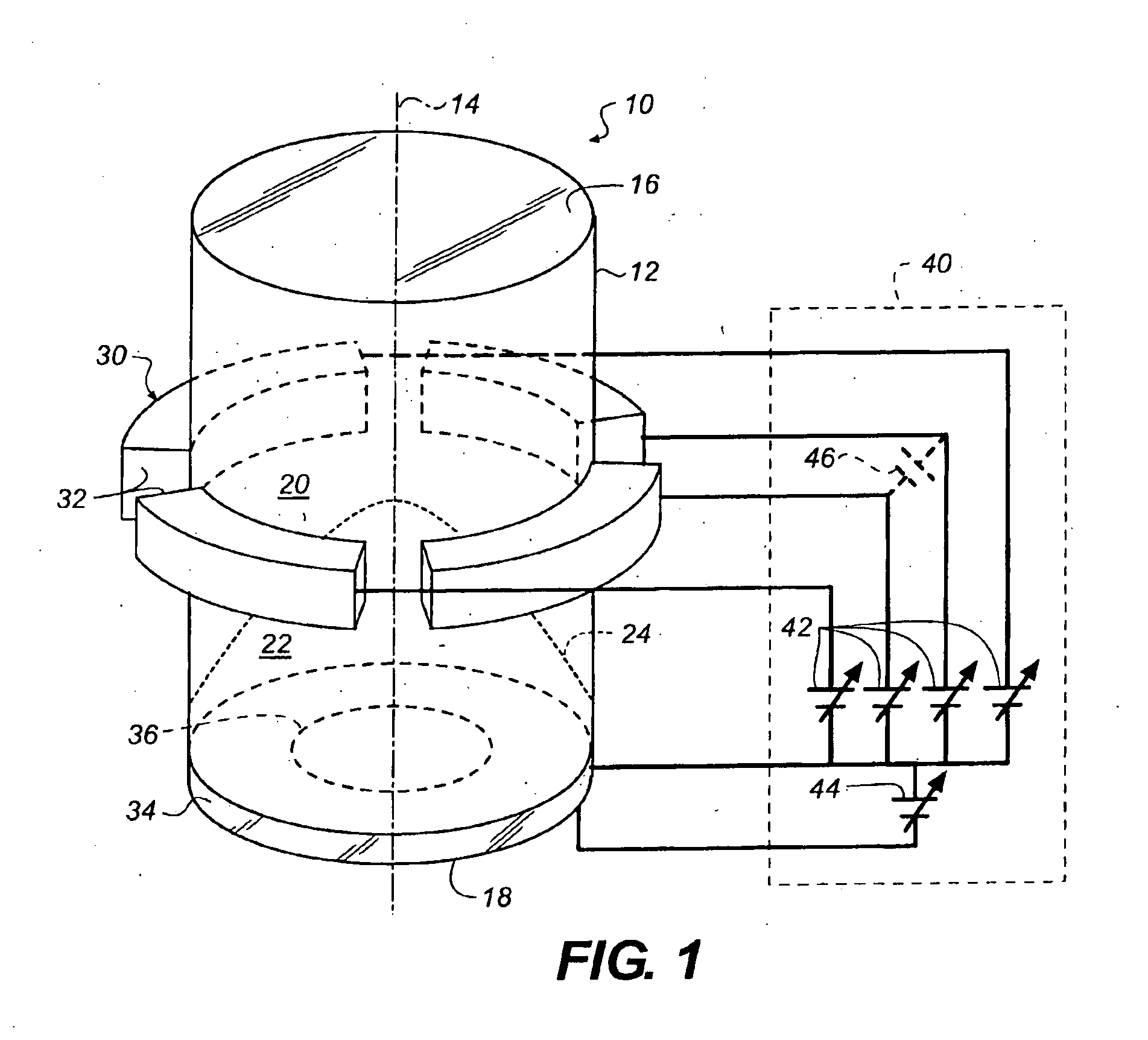
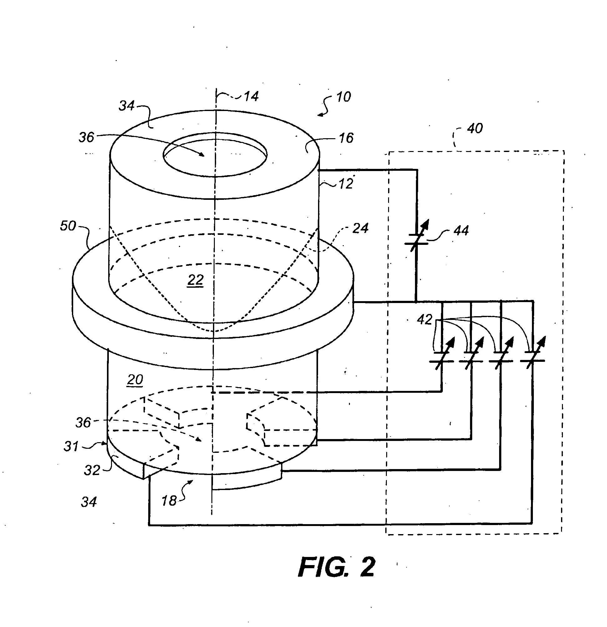
[0062]The variable focal length lens of FIG. 1 comprises a chamber 10 in the form of a straight cylinder, with a side wall 12 extending parallel to its axis 14, and with end walls 16 and 18 perpendicular to the axis 14.

[0063]The end walls are made of light transparent material and constitute the entry and exit surfaces of the lens. The entry and exit surfaces can in particular be comprised of solid fixed focal length lenses. The side wall 12 is preferably made of an electric insulating material.

[0064]An annular electrode 30, formed of several segments 32 mutually isolated, is arranged around the chamber 10. More precisely the segments are arranged against the side wall 12 which thus acts as an electric insulating support. The number of segments is preferably greater than or equal to three.

[0065]The len...


PUM


Abstract

The invention relates to a variable focal length lens with a chamber (10) having symmetry of revolution around an axis (14) and containing one first transparent fluid (20) and one second transparent fluid (22) that have different optical indices and are immiscible, so as to form a meniscus (24), and that have different electrical conductivities, and means (30, 40) to modify the curvature of the meniscus.According to the invention, the means to modify the curvature of the meniscus comprises means of applying an electric field dissymmetrical in relation to the axis of said chamber.The invention has applications in the production of cameras.

Description

FIELD OF THE INVENTION[0001]The present invention relates to lenses with variable focal length. More precisely, it relates to lenses formed by the combination of two transparent immiscible liquids, which have different optical indices and constitute a meniscus at their interface. The focal length of these lenses can be modified by means of an electric field applied to the liquids.[0002]The possibility of quickly and easily modifying the focal length of the lenses, by means of an electric control, is particularly advantageous for all equipment in which it is difficult to integrate bulky optical systems or motors intended to move the optical systems mechanically.[0003]The invention finds applications in the manufacture of lenses or optical equipments, and in particular recording equipment such as digital cameras or phonecams.BACKGROUND OF THE INVENTION[0004]The state of the art is illustrated by documents (1) and (2), whose references are given at the end of the description.[0005]The ...

Claims


Application Information

Patent Timeline
IPC IPC(8): G02B27/64G02B3/14
CPCG02B26/005G02B3/14
Inventor WEBER, ETIENNE N.TOUCHARD, NICOLAS P.
Owner EASTMAN KODAK CO
Learn More