Use of a focusing vortex lens as the objective in spiral phase contrast microscopy

a vortex lens and phase contrast technology, applied in the field of phase contrast microscopy, can solve the problems of limiting the chromatic range of the microscope, the type of source, and the cost of phase contrast by means of defocus, and achieve the effect of simple, efficient and inexpensiv

Inactive Publication Date: 2009-05-28
UCHICAGO ARGONNE LLC
View PDF9 Cites 30 Cited by
  • Summary
  • Abstract
  • Description
  • Claims
  • Application Information

AI Technical Summary

Benefits of technology

[0012]In accordance with features of the invention, the invention provides a simple, efficient, and inexpensive enhancement of standard microscopes and microscopy methods by adding spiral phase contrast capability. The focusing vortex lens is substituted for the usual objective lens in a standard microscope generally without requiring other changes to the microscope. Conventional methods of phase contrast microscopy require additional optics, coherent sources, reference waves, or iterative methods in addition to the usual equipment used by microscopes.

Problems solved by technology

A significant practical problem for phase contrast microscopy is to find an effective way of separating the incident or direct light from that diffracted by the object.
Phase contrast by means of defocus comes at the expense of object resolution.
These restrictions limit the chromatic range of the microscope, the imaging resolution, the types of sources that can be used, and the types of objects that can be imaged with phase contrast.

Method used


Image

  • Use of a focusing vortex lens as the objective in spiral phase contrast microscopy
  • Use of a focusing vortex lens as the objective in spiral phase contrast microscopy
  • Use of a focusing vortex lens as the objective in spiral phase contrast microscopy

Examples


Embodiment Construction

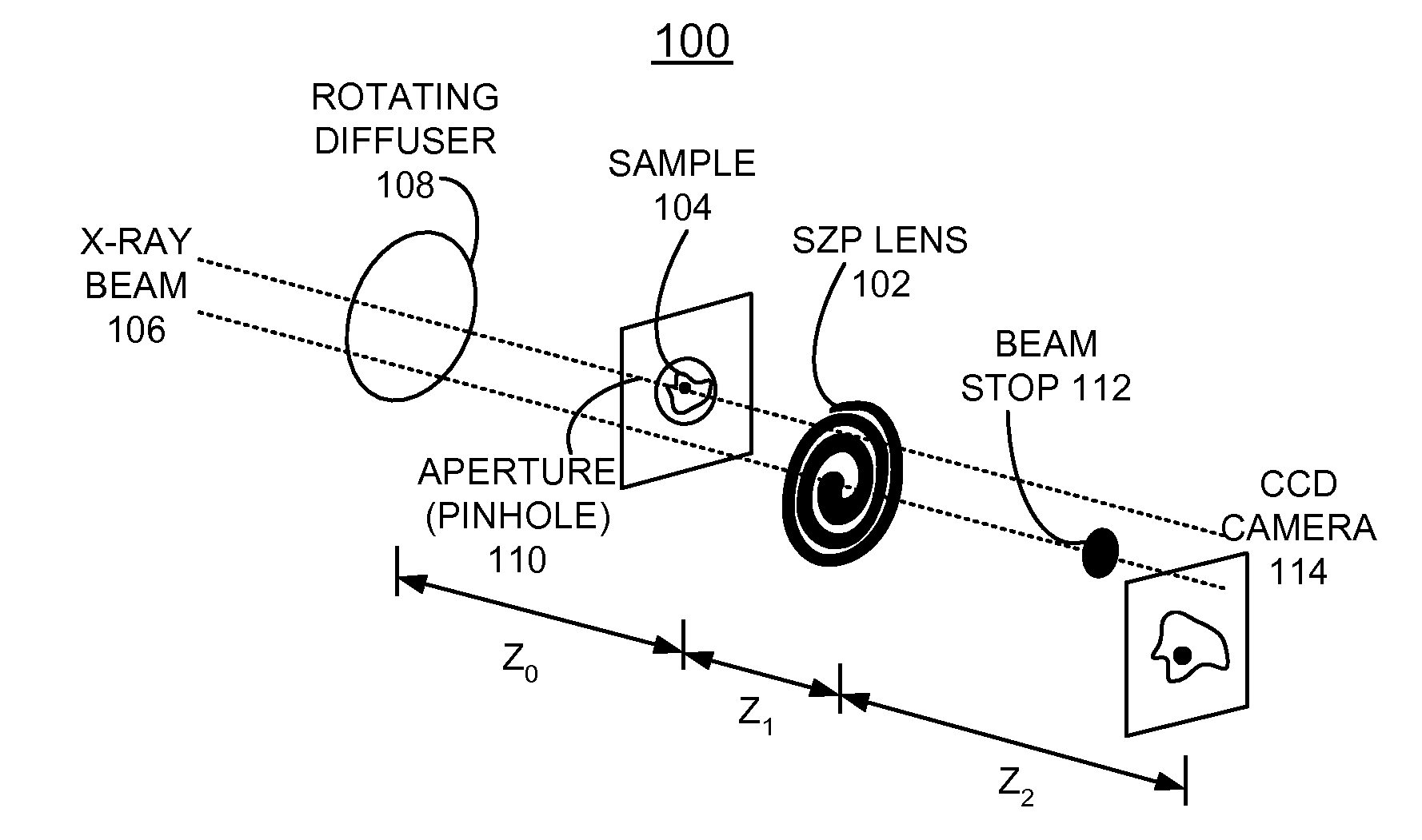
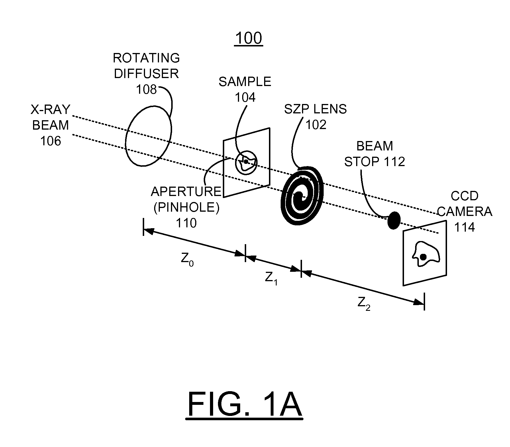
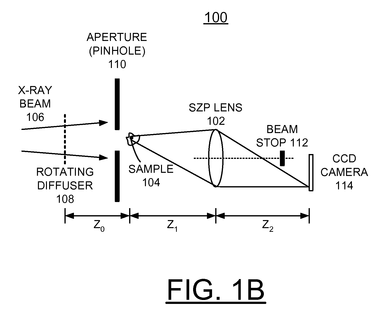
[0023]In accordance with features of the invention, a micron-scale full-field spiral phase microscope is provided with a hard x-ray beam replacing the microscope objective lens with a focusing vortex lens. A refractive focusing vortex lens has helical phase steps fabricated into the curved surface of a conventional refractive lens. A diffractive focusing vortex lens has phase-shifting spiral zones instead of the circular zones in a conventional diffractive lens. Both types of lenses focus and impart a helical phase to the incident illumination. This helical phase allows the object to be imaged with azimuth-independent phase contrast and without additional optics, source requirements, reference waves, or iterative methods. A significant and principal benefit of this method is that it is applicable to all microscopes by substituting a focusing vortex lens in place of the usual objective lens. Advantages of this method hold for practical full-field x-ray microscope and this optical met...


PUM


Abstract

A method and objective apparatus are provided for implementing an enhanced phase contrast microscope. A focusing vortex lens, defined by a diffractive spiral zone plate (SZP) lens, is used for the objective for the phase contrast microscope. The SZP lens focuses and imparts a helical phase to incident illumination to image the specimen with spiral phase contrast. The spiral phase contrast microscope is sensitive to phase gradients in all sample axes. Replacing the objective of a microscope with the diffractive SZP lens of the invention immediately provides existing instruments with spiral phase contrast capability.

Description

CONTRACTUAL ORIGIN OF THE INVENTION[0001]The United States Government has rights in this invention pursuant to Contract No. W-31-109-ENG-38 between the United States Government and The University of Chicago and / or pursuant to Contract No. DE-AC02-06CH11357 between the United States Government and UChicago Argonne, LLC representing Argonne National Laboratory.FIELD OF THE INVENTION[0002]The present invention relates to an improvement in phase contrast microscopy, and a method and apparatus for implementing an enhanced phase contrast microscope.DESCRIPTION OF THE RELATED ART[0003]Phase contrast microscopy is widely used to image the structure of weakly absorbing objects with many types of radiation, such as visible light, electrons, x-rays, neutrons, and the like. The most popular methods used for phase contrast microscopy are based on those of Zernike and Nomarski. Other methods are based on defocus, configured detectors, interferometry, holography, or coherent diffraction.[0004]Phas...

Claims


Application Information

Patent Timeline
Patent Type & Authority Applications(United States)
IPC IPC(8): G02B27/44G21K1/06
CPCG02B5/189G02B21/14G21K2207/005G21K2201/06G21K2201/067G21K1/06
Inventor MCNULTY, IAN
Owner UCHICAGO ARGONNE LLC
Why Eureka
Try Eureka