Illuminating Equipment Using High Power LED With High Efficiency of Heat Dissipation

a technology of heat dissipation efficiency and lighting equipment, which is applied in the field of packaging systems, can solve the problems of increasing the cost of installation and replacement, so as to achieve the effect of increasing the heat dissipation efficiency of lighting equipment, high power, and easy installation and replacemen

Inactive Publication Date: 2009-05-28
ENRAYTEK OPTOELECTRONICS
View PDF12 Cites 23 Cited by
  • Summary
  • Abstract
  • Description
  • Claims
  • Application Information

AI Technical Summary

Benefits of technology

[0008]The efficiency of heat dissipation of the illuminating equipment, according to the present invention, is greatly increased. Although the illuminating equipment adopts high power LED, a great deal of heat which is generated during light emitting can be effectively dissipated by the heat-conducting device and the heat-dissipating fin to maintain the emitting efficiency of the LED. Moreover, the present invention provides a plug and play packaged system which is suitable for various illuminating equipment, and users can easily install and replace the packaged system.

Problems solved by technology

The difference between the high illumination LED packages and the traditional LED bulbs is that the high illumination LED uses larger emitter chip, but it also correspondingly causes higher power requirement.
However, as a result of the shape, the dimension, and the power requirement of the high illumination LED, the LED manufacturers have encountered unexpected difficulties on manufacturing.
Although the package is capable of generating higher illumination than the traditional LED bulb, it also generates a greater amount of heat.
If the heat can not be dissipated effectively, the emitter chip may be damaged.
Although these components are capable of dissipating heat effectively, their volume is often too large to be incorporated into compact illuminating equipments, such as a flashlight or floodlight.
At the same time, because the circuit board which disposes heat-conducting boards also includes many other heat sink material, it is very difficult to weld the heat-conducting board with the circuit board without applying a great deal of heat.

Method used


Image

  • Illuminating Equipment Using High Power LED With High Efficiency of Heat Dissipation
  • Illuminating Equipment Using High Power LED With High Efficiency of Heat Dissipation
  • Illuminating Equipment Using High Power LED With High Efficiency of Heat Dissipation

Examples


Embodiment Construction

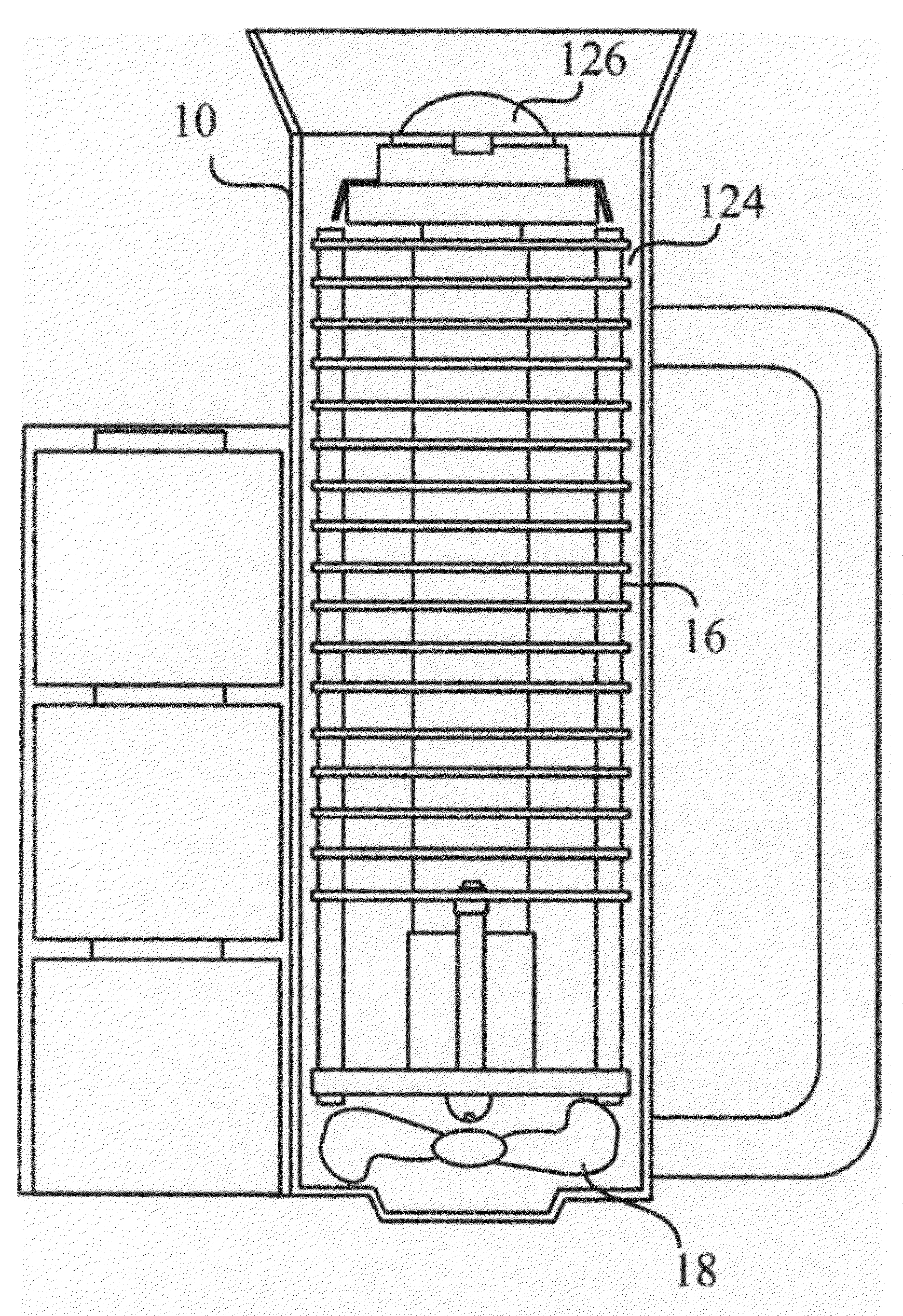
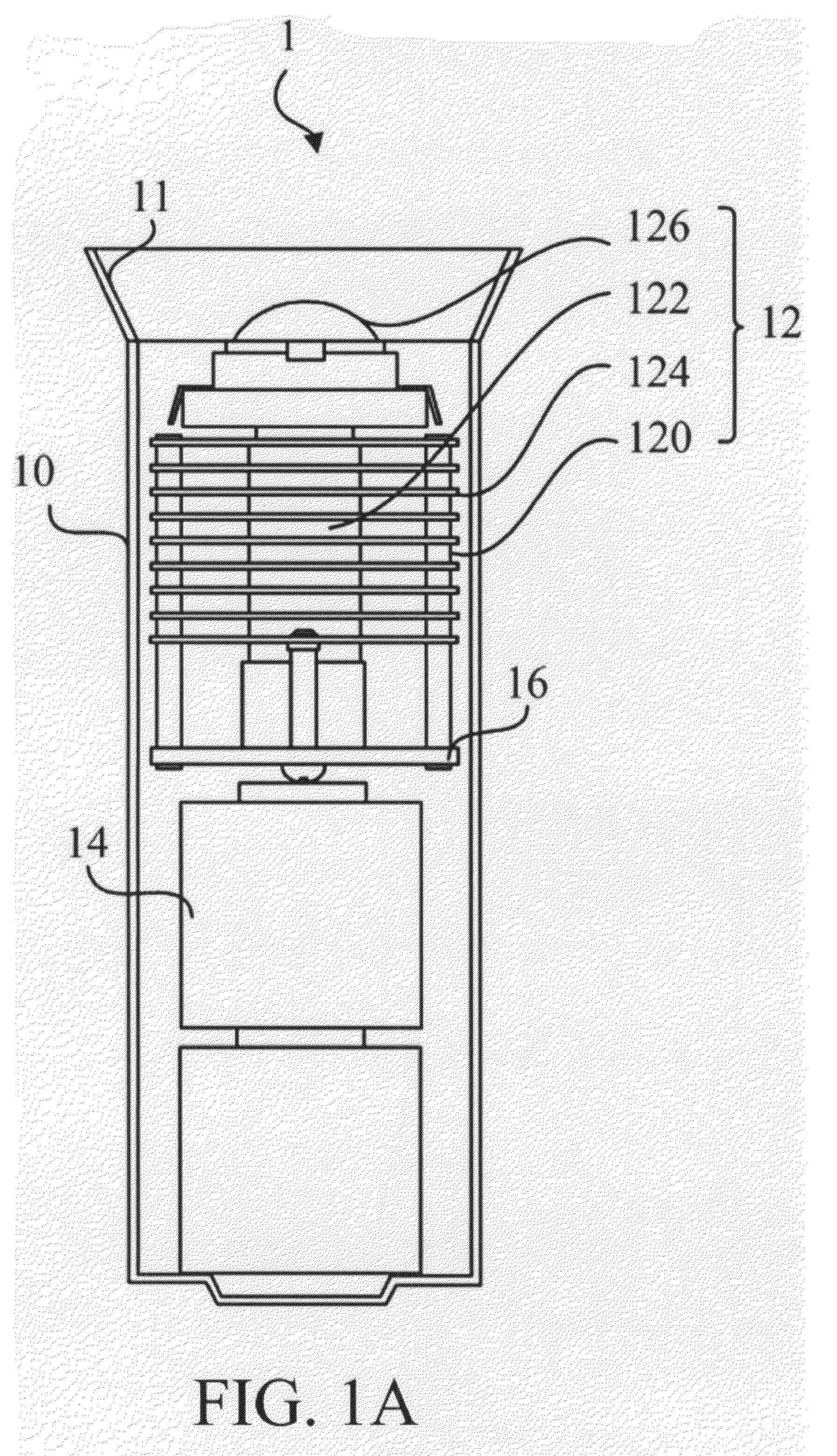
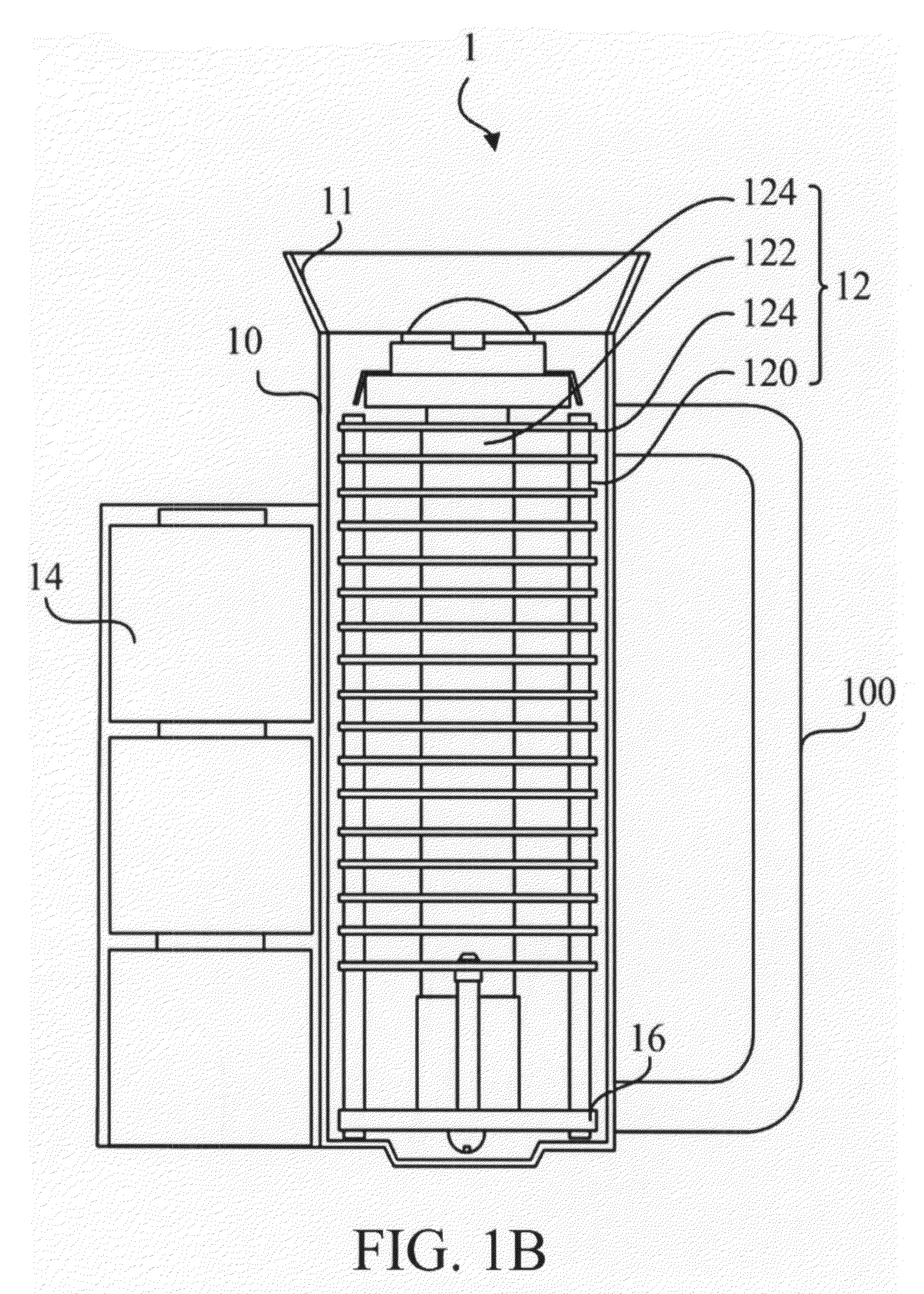
[0032]The purpose of the present invention is to provide a packaged system; the packaged system is for packaging a light-emitting apparatus and is capable of further integrating in an illuminating equipment. Particularly, the present invention relates to a packaged system; the packaged system is used for packaging the high power LED,; it also provides a highly efficient heat-dissipating apparatus and collocates the integrated power supply and the reflector apparatus for further applications on various projecting illuminating equipments, such as a flashlight or floodlight. The preferred embodiments according to the present invention will be described in detail as follows.

[0033]Referring to FIG. 1A, FIG. 1A is a cross-sectional view of the illuminating equipment 1 according to the first preferred embodiment of the invention. The illuminating equipment 1 comprises a housing 10, a reflector 11, a packaged system 12, and a power supply 14. The housing 10 thereon defines a head end. The r...


PUM


Abstract

The invention provides a packaged system that is suitable for a LED package of high power. The packaged system further includes a heat-conducting device surrounded by at least one heat-dissipating fin to effectively dissipate the heat generated by the high power LED package. The packaged system with high efficiency of heat dissipation can be incorporated into various projecting illuminating equipments, such as a flashlight or floodlight, by simply installing the present invention into a housing and providing power connection thereto.

Description

FIELD OF THE INVENTION[0001]The present invention relates to a packaged system; the packaged system is for packaging a light-emitting apparatus and is capable of further integrating an illuminating equipment. Particularly, the present invention relates to a packaged system; the packaged system is for packaging the high power LED, and it provides a highly efficient heat-dissipating apparatus and collocates the integrated power supply and the reflector apparatus for further applications on various projecting illuminating equipments, such as a flashlight or floodlight.BACKGROUND OF THE INVENTION[0002]Presently, there are many manufacturers who invest in manufacturing high illumination LED packages with different shapes. The difference between the high illumination LED packages and the traditional LED bulbs is that the high illumination LED uses larger emitter chip, but it also correspondingly causes higher power requirement. In general, the packages are originally designed to replace t...

Claims


Application Information

Patent Timeline
Patent Type & Authority Applications(United States)
IPC IPC(8): F21V29/02F21V29/00F21Y101/00H01L33/60H01L33/64
CPCF21L4/027F21L4/045F21S8/02F21V29/004F21V29/83F21Y2101/02F21V29/02F21V29/767F21V29/773F21V29/006F21Y2115/10F21V29/89F21V29/763F21V29/51
Inventor CHEN, JEN-SHYAN
Owner ENRAYTEK OPTOELECTRONICS
Why Eureka
Try Eureka