Imaging apparatus

a technology of imaging apparatus and spherical tube, which is applied in the direction of radiation beam directing means, instruments, applications, etc., can solve the problems of disturbed relative positional relationship

Inactive Publication Date: 2009-05-28
CANON KK
View PDF2 Cites 44 Cited by
  • Summary
  • Abstract
  • Description
  • Claims
  • Application Information

AI Technical Summary

Benefits of technology

[0008]Accordingly, the present invention seeks to provide an imaging apparatus in which the relative positional relationship between an X-ray detector and an optical imaging unit can be corrected, thereby bringing the positions of an X-ray image and optical image of a subject into registration.

Problems solved by technology

However, there is the possibility that this relative positional relationship will be disturbed, particularly in the case of a portable X-ray imaging apparatus.

Method used


Image

  • Imaging apparatus
  • Imaging apparatus
  • Imaging apparatus

Examples


Embodiment Construction

[0018]Various exemplary embodiments, features and aspects of the present invention will be described in detail below with reference to the drawings.

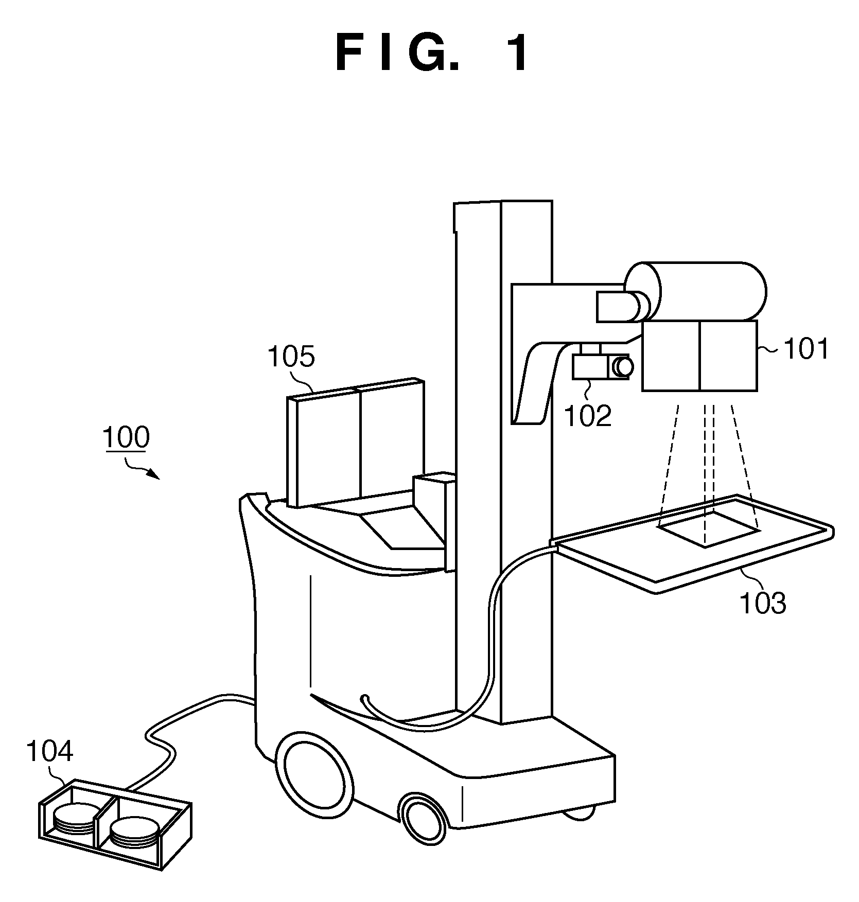
[0019]FIG. 1 is a perspective view illustrating the external appearance of an X-ray diagnosis cart 100 according to an embodiment of the present invention.

[0020]The X-ray diagnosis cart 100 is a portable X-ray imaging apparatus that includes an X-ray generator 101, a TV camera 102, an X-ray detector 103, a foot pedal 104 and a display unit 105.

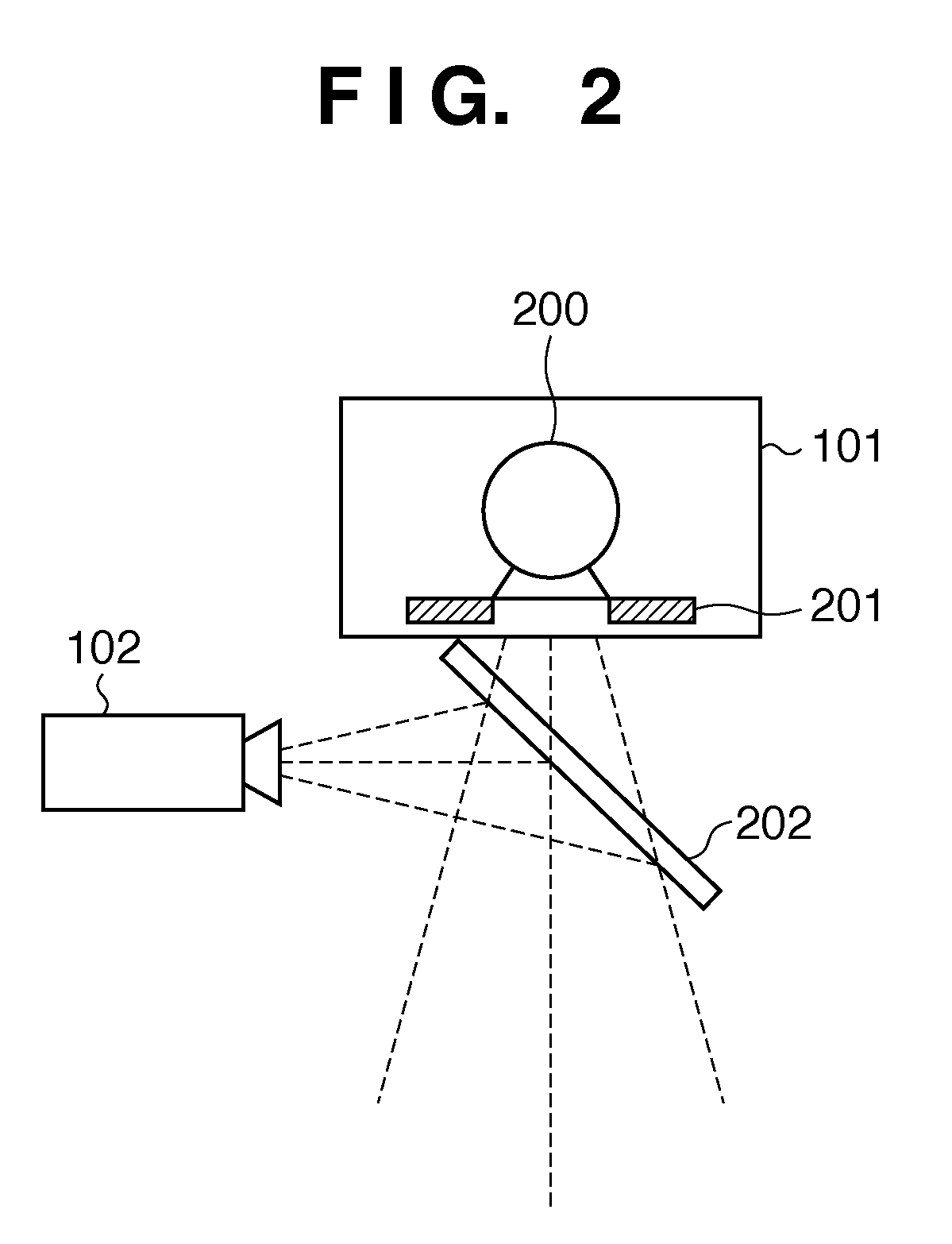
[0021]The X-ray generator 101 has a mechanism for generating X-rays that irradiate a subject. Specifically, the X-ray generator 101 includes an X-ray tube serving as an X-ray source, and an X-ray aperture for delimiting the zone of X-ray irradiation.

[0022]The TV camera 102 serving as an optical imaging unit is placed at a position conjugate with respect to the X-ray tube via a half-mirror provided inside the X-ray generator 101 and is capable of capturing the optical image of the surface of a subje...


PUM


Abstract

An imaging apparatus in which positions of an X-ray image and optical image of a subject can be brought into registration with each other is provided. A half-mirror is provided between the X-ray source and subject and is configured to pass X-rays and reflect visible light. A TV camera captures the optical image of the surface of the subject reflected by the half-mirror. A display unit displays the optical image captured by the TV camera together with a reference mark indicating the reference position of this optical image, and displays, in superimposed form, an X-ray image obtained by capturing a prescribed reference object as a subject by using an X-ray imaging unit. An adjusting unit adjusts position and attitude of an X-ray detector in such a manner that the reference object displayed by the display unit will coincide with the reference mark.

Description

BACKGROUND OF THE INVENTION[0001]1. Field of the Invention[0002]The present invention relates to an imaging apparatus for capturing a fluoroscopic image of a subject.[0003]2. Description of the Related Art[0004]Flat-panel detectors that output digital data are now widely used instead of conventional screen / film systems in recent X-ray imaging systems. A flat-panel detector is so adapted that electric charge (referred to as “signal charge” below) proportional to X-ray dosage accumulates in each of a number of two-dimensionally arrayed detecting elements, and the accumulated signal charges are read out to a signal output line sequentially via TFTs (thin-film transistors) having a switching function. Signal charge that has been output to the signal output line is subjected to a charge-to-voltage conversion and is displayed upon being converted to a digital signal by an A / D converter.[0005]An X-ray imaging apparatus can be classified broadly into three types, namely an upright type in w...

Claims


Application Information

Patent Timeline
Patent Type & Authority Applications(United States)
IPC IPC(8): H05G1/64
CPCA61B6/08A61B6/12A61B6/4233A61B6/583A61B6/5235A61B6/5247A61B6/4405
Inventor NISHII, YUICHIABE, MASAHIROSHIOZAWA, HIDETOSAKO, TSUKASA
Owner CANON KK
Why Eureka
Try Eureka