Muffle for the production of dental prostheses

Inactive Publication Date: 2009-05-28
IVOCLAR VIVADENT AG
View PDF13 Cites 6 Cited by
  • Summary
  • Abstract
  • Description
  • Claims
  • Application Information

AI Technical Summary

Benefits of technology

[0027]Advantageously, it can moreover be envisaged that the diameter of the plunger is narrower in the upper region than in the lower region. This design is beneficial for the transmission of force from the sender via the plunger onto the embedding compound in a relatively wide receiving space (diameter greater than 10 mm, preferably approx. 27 mm).
[0028]At present, plungers are commercially available that have a diameter of approx. 10 mm and a height of approx. 30 to 40 mm, thus only press directly on a commercially available blank, and several blanks can be

Problems solved by technology

Generally when using muffles from the prior art or other usual muffles, numerous problems or disadvantages arise.
The main problem is the production of large bridges in one piece.
The existing muffles do not offer sufficient space for larger prosthetic structures.
In particular, the receiving space for the charge in the muffle only has a size of up to 10 cm3 in the largest muffles currently known, which allows a maximum charge of ceramic weighing about 20 g. However, a larger charge is often required for overpressing extensive bridges.
A problem that arises with large dental prostheses is the development of thermal stress cracks, which arise on account of the

Method used


Image

  • Muffle for the production of dental prostheses
  • Muffle for the production of dental prostheses
  • Muffle for the production of dental prostheses

Examples


Embodiment Construction

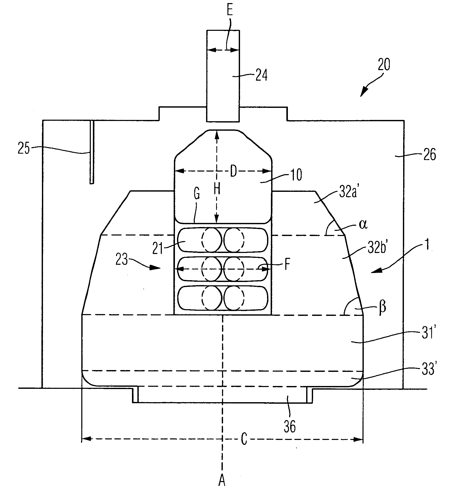
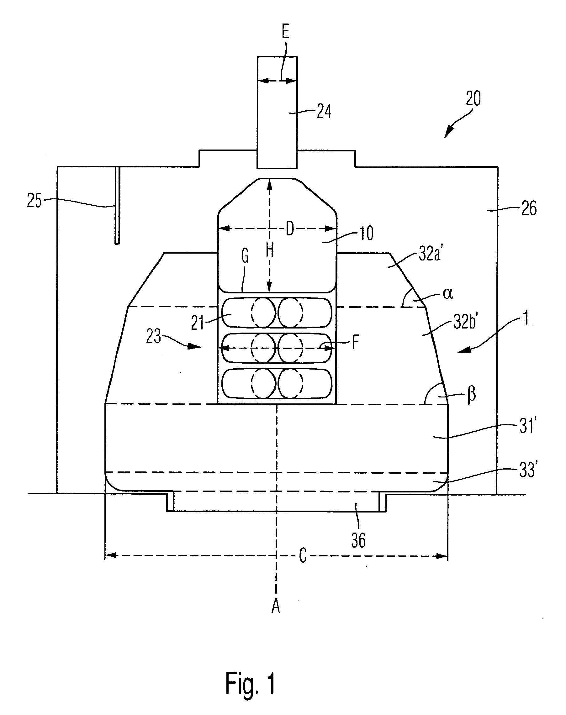
[0083]FIG. 1 shows a cross section of the concrete embodiment of a muffle according to the invention. In this case the furnace chamber 26, of the ceramic pressing furnace has a diameter of 9.8 cm (the furnace EP5000 from the company Ivoclar serves for example as the ceramic pressing furnace). Viewing from top to bottom, in the uppermost region the muffle has a truncated-cone-shaped body 32a′ with a cone angle of 62°. This is followed by a truncated-cone-shaped body 32b′ with a cone angle of 79°. In this case, these two together have a height of 4 cm. Next there is a cylindrical body 31′ and then a curved, rotationally symmetrical body 33′, which together have a height of 2.7 cm. For fitting the muffle in this kind of ceramic pressing furnace, a base 36 is also provided at the bottom, and this holds the complete muffle in place during the pressing process. The diameter of the complete muffle 1 is 8 cm in the cylindrical region 31. The periphery of the receiving space 23 forms the inn...


PUM

PropertyMeasurementUnit
Fractionaaaaaaaaaa
Fractionaaaaaaaaaa
Fractionaaaaaaaaaa

Abstract

Muffle (1) for the production of dental prostheses (2), said muffle (1) being a body that is substantially rotationally symmetrical about the muffle axis (A), characterized in that the proportion of cylindrical surface regions (31) about the muffle axis (A)—relative to the total surface area of the outer contour (3) of the muffle (1)—is less than 30%, preferably less than 20%.

Description

CROSS-REFERENCE TO RELATED APPLICATIONS[0001]This application claims foreign priority benefits under 35 U.S.C. §119(a)-(d) from Austrian patent application ser. no. A 1773 / 2007 filed Nov. 5, 2007.TECHNICAL FIELD[0002]The invention relates to a muffle for the production of dental prostheses, the muffle being a substantially rotationally symmetrical body about the muffle axis. Moreover, the invention relates to a device and a method of production of a muffle. The invention further relates to a plunger for the production of dental prostheses in muffles, said plunger being a substantially rotationally symmetrical body, and a device and a method of production of said plunger. The invention further relates to a method and a device for the production of dental prostheses with muffles and plungers according to the invention.BACKGROUND OF THE INVENTION[0003]Numerous muffles, which are of substantially cylindrical shape, are already known from the prior art for the production of dental prosth...

Claims


Application Information

Patent Timeline
IPC IPC(8): A61C9/00A61C13/20
CPCA61C13/20A61K31/05F27B17/025A61K36/87A61K36/45
Inventor GRITSCH, HARALDWORISHOFER, MAXZOBLER, CHRISTOPH
Owner IVOCLAR VIVADENT AG
Why Eureka
Try Eureka