Automotive wire

a technology for automotive wires and wires, applied in the direction of insulated conductors, cables, conductors, etc., can solve the problems of automotive wire cupolating, cracks, rusting, etc., and achieve the effects of high breaking strength and electrical conductivity, superior corrosion resistance, and narrow diameter

Active Publication Date: 2013-05-02
THE FUJIKURA CABLE WORKS LTD
View PDF6 Cites 5 Cited by
  • Summary
  • Abstract
  • Description
  • Claims
  • Application Information

AI Technical Summary

Benefits of technology

[0030]According to the present invention, since a wire material formed from a core and a metal film that covers the surface of the core is used as a conductor of an automotive wire, and carbon steel is employed for the core, an automotive wire can be provided that has high breaking strength and electrical conductivity while realizing a narrow diameter, has superior corrosion resistance, and is resistant to bending.

Problems solved by technology

However, in the confined spaces within automobiles, automotive wire is wired in a bent state, and is frequently wrapped around components within the automobile.
However, when the automotive wire described in the above-mentioned Patent Document 4 was wrapped around a component, cracks could occur in the Cu plating layer of the automotive wire.
These cracks can cause strength deterioration and rusting of the automotive wire.

Method used


Image

  • Automotive wire
  • Automotive wire
  • Automotive wire

Examples


first embodiment

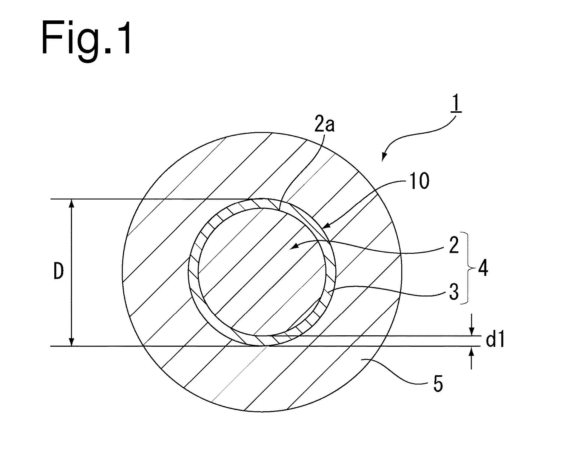
[0038]The following provides a detailed explanation of a first embodiment of the present invention with reference to the drawings. FIG. 1 is a schematic cross-sectional view showing an automotive wire according to the first embodiment of the present invention.

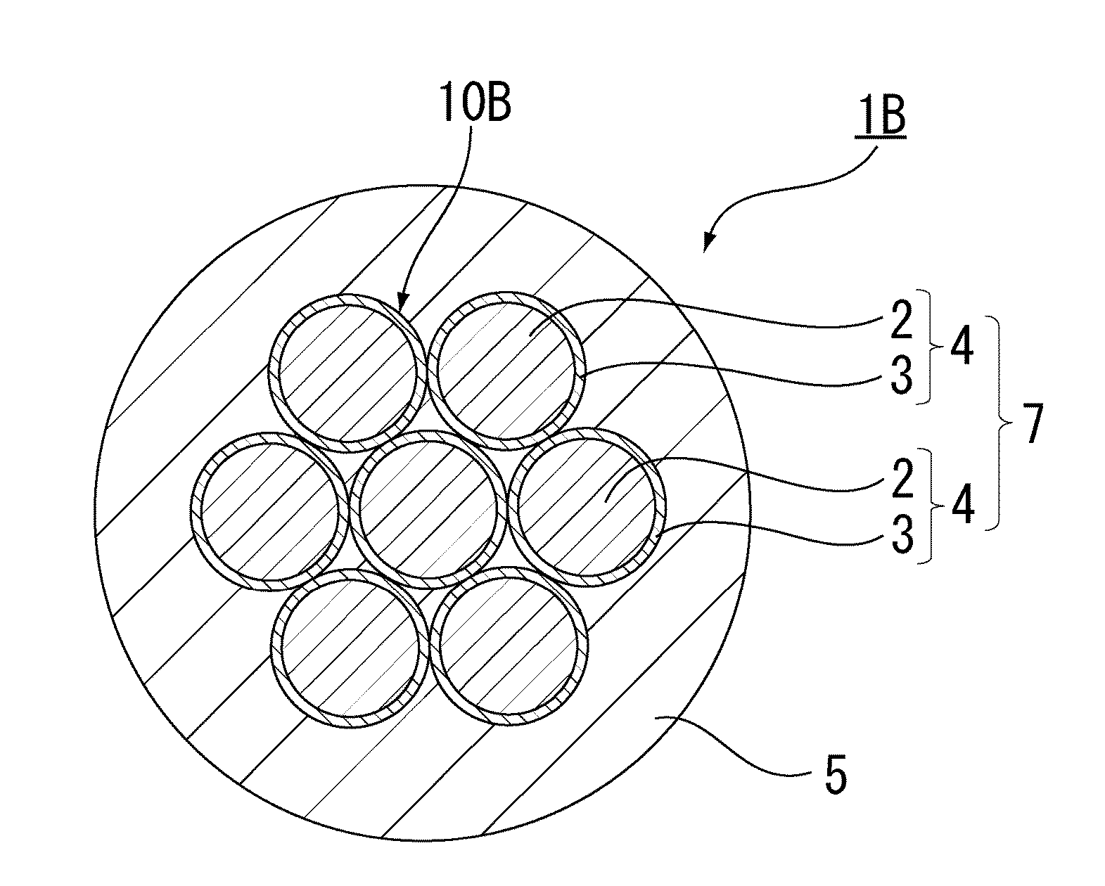
[0039]As shown in FIG. 1, an automotive wire 1 of the present invention is composed of a conductor 10 composed of a solid wire 4 for conducting electricity, and an insulator 5 for protecting the conductor 10 and insulating from the outside. The solid wire 4 is composed of a core 2 and a metal layer 3 that covers a surface 2a of the core 2. In the automotive wire 1 of the present invention, the core 2 is composed of carbon steel.

[0040]Although there are no particular limitations thereon, the carbon content in the carbon steel is preferably 0.1% by mass to 1.0% by mass, and more preferably 0.69% by mass to 0.76% by mass. Hard steel wire materials (steel wire rods—high carbon (SWRH)), for example, are used as carbon steel having a...

second embodiment

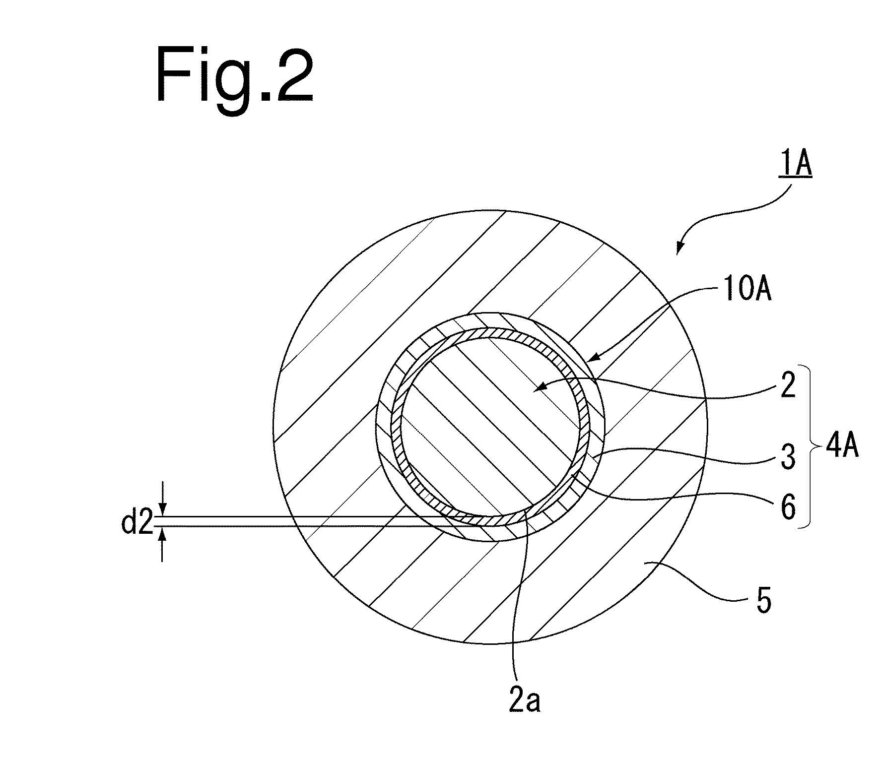
[0066]Next, a detailed explanation is provided of an automotive wire according to a second embodiment of the present invention. Furthermore, constituent elements of the second embodiment that are the same or similar to those of the first embodiment are indicated with the same reference symbols, and duplicate explanations thereof are omitted. FIG. 2 is a schematic cross-sectional view of an automotive wire 1A according to the second embodiment.

[0067]As shown in FIG. 2, the automotive wire 1A according to the second embodiment of the present invention differs from the automotive wire 1 of the first embodiment in that a nickel (Ni) plating layer 6 is further provided between the core 2 composed of carbon steel and the metal film 3 composed of Cu plating. Namely, as shown in FIG. 2, a conductor 10A is composed of a solid wire 9A, and the solid wire 4A is composed of the core 2, the metal film 3, and the Ni plating layer 6 provided between the core 2 and the metal film 3.

[0068]In this ca...

examples

[0085]Although the following provides a more specific explanation of the contents of the present invention by listing examples thereof while comparing with comparative examples that are outside the scope of the present invention, the present invention is not limited to the following examples.


PUM

PropertyMeasurementUnit
thicknessaaaaaaaaaa
breaking strengthaaaaaaaaaa
thicknessaaaaaaaaaa

Abstract

The present invention is an automotive wire provided with a conductor including at least one solid wire composed of a core and a metal film that covers the surface of the core, and an insulator that covers the conductor, wherein the core is composed of carbon steel, and the metal film has a thickness of 12.4 μm to 29.6 μm.

Description

CROSS REFERENCE TO RELATED APPLICATIONS[0001]This application is a Continuation of National Stage of International Application No. PCT / JP2011 / 064299 filed Jun. 22, 2011, claiming priority based on Japanese Patent Application No. 2010-143717 filed Jun. 24, 2010, the contents of all of which are incorporated herein by reference in their entirety.TECHNICAL FIELD[0002]The present invention relates to an automotive wire used in, for example, wire harnesses.BACKGROUND ART[0003]The use of electronics is becoming increasingly prevalent in the field of automobiles in recent years, and the wiring used to connect various types of electronic devices installed in vehicles is increasing in both quantity and complexity. Although automotive wires referred to as wire harnesses are used to connect these electronic devices, accompanying the growing prevalence of electronics in vehicles as mentioned above, these wire harnesses are becoming increasingly large.[0004]On the other hand, together with the g...

Claims


Application Information

Patent Timeline
Patent Type & Authority Applications(United States)
IPC IPC(8): H01B7/00
CPCH01B7/0009
Inventor KIZAKI, TAKESHI
Owner THE FUJIKURA CABLE WORKS LTD
Why Eureka
Try Eureka