Method of manufacturing head of inkjet printer

Inactive Publication Date: 2005-08-02
HEWLETT PACKARD DEV CO LP
View PDF5 Cites 6 Cited by
  • Summary
  • Abstract
  • Description
  • Claims
  • Application Information

AI Technical Summary

Benefits of technology

[0014]The present invention has been made to overcome the above-mentioned problems of the related art, and accordingly, it is an object of the present invention to provide a method

Problems solved by technology

However, the above-described method has a problem.
That is, since the nozzle plate is attached to the heater-formed substrate after the nozzle is formed in the nozzle plate, it is very difficult to increase the positional accuracy of the nozzle.
Because of the low positional accuracy of the nozzle, when the nozzle, the ink chamber and/or the ink feeding passage of the ink chamber are not aligned with each other accurately, the orientation of the ink droplets is deviated when the ink droplets are ejected through the nozzle, and as a result, a printing image could not have a desirable resolution.
Although the nozzle, the ink chamber and/or the ink feeding passage of the substrate are aligned easily, this method also has a problem.
That is, since the nozzle is formed in the nozzle plate after the nozzle plate is attached to the heater-formed substrate, the alignment of the heater on the substrate and the nozzle of the nozzle plate becomes difficult.
Also, according to the another suggestion, since the nozzle is formed after the nozzle plate is attached to the substrate,

Method used


Image

  • Method of manufacturing head of inkjet printer
  • Method of manufacturing head of inkjet printer
  • Method of manufacturing head of inkjet printer

Examples


Embodiment Construction

[0029]Reference will now be made in detail to the present preferred embodiments of the present invention, examples of which are illustrated in the accompanying drawings, wherein like reference numerals refer to the like elements throughout. The embodiments are described in order to explain the present invention by referring to the figures.

[0030]The preferred embodiment of the present invention will now be described with reference to the drawings.

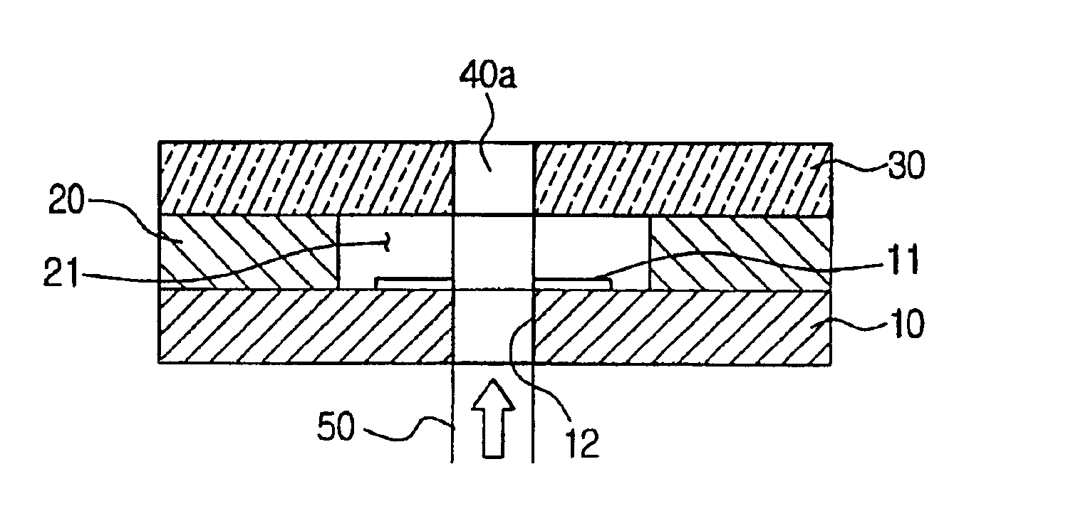
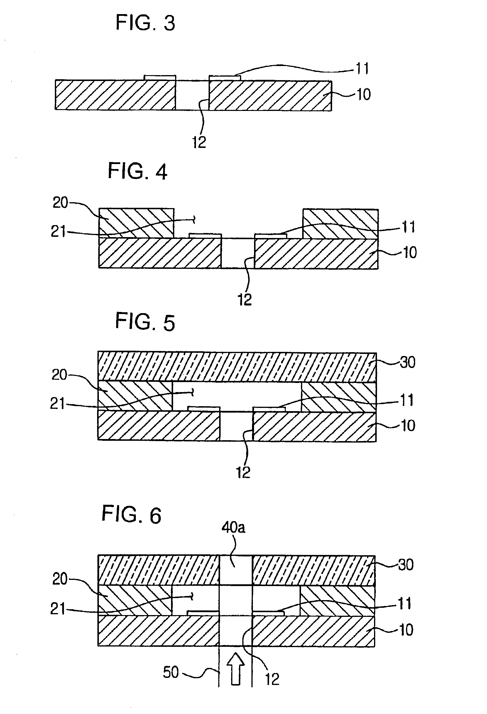
[0031]FIGS. 3 through 6 show a method of manufacturing a head of an inkjet printer according to an embodiment of the present invention. In the drawings, a reference numeral 10 refers to a substrate, 20 is an ink chamber wall, 30 is a nozzle plate and 40 is a nozzle.

[0032]of manufacturing the head of the inkjet printer of the present invention, first] First, as shown in FIG. 3, a heater 11 is formed on the substrate 10, while an ink feeding passage 12 is vertically formed through the substrate 11 in an area in the middle of where the heater 1...


PUM

PropertyMeasurementUnit
Thicknessaaaaaaaaaa
Diameteraaaaaaaaaa
Areaaaaaaaaaaa

Abstract

A method of manufacturing a head of an inkjet printer includes forming a heater on a substrate and also forming an ink feeding passage through the substrate in a vertical relation to a surface where the heater is formed, forming an ink chamber communicating with the ink feeding passage of the substrate; attaching the substrate to the nozzle plate, and forming a tapered nozzle in the nozzle plate, the tapered nozzle being narrower in diameter in an inside of the nozzle plate than an outside of the nozzle plate, by radiating a laser beam from inside toward the outside of the nozzle plate, wherein the substrate is used as a mask. Since the nozzle is formed by radiating the laser beam to the nozzle plate through the ink feeding passage of the substrate after attaching the nozzle plate to the substrate, the accuracy of the nozzle in form and position improves, and the nozzle of desirable structure of the improved ink discharge efficiency can be obtained by radiating the laser beam only once. Also, the manufacturing process becomes simpler, and due to improved manufacturing process, the productivity increases.

Description

CROSS-REFERENCE TO RELATED APPLICATIONS[0001]This application claims the benefit of Korean No. 2001-75624, filed Dec. 1, 2001, in the Korean Industrial Property office, the disclosure of which is incorporated herein by reference.BACKGROUND OF THE INVENTION[0002]1. Field of the Invention[0003]The present invention relates to a method of manufacturing a head of an inkjet printer, and more particularly, to a method of manufacturing a head of an inkjet printer and forming a nozzle on a nozzle plate using a laser beam radiated on the nozzle plate through an ink passage of a substrate.[0004]2. Description of the Related Art[0005]Generally, inkjet printers are categorized into a bubble-jet type, a Mach type, a thermal type and a thermal compression type according to ways of discharging ink. The bubble-jet type printer ejects ink droplets by means of bubbles generated by a heating element heating liquid ink. The bubble-jet type printer includes a head having a nozzle plate formed at one sid...

Claims


Application Information

Patent Timeline
IPC IPC(8): H04L1/00B41J2/05
CPCB41J2/1603B41J2/1634B41J2/1639B41J2/1642Y10T29/496Y10T29/49401Y10T29/49083Y10T29/49002B41J2/05
Inventor KIM, ILCHO, SEO-HYUN
Owner HEWLETT PACKARD DEV CO LP
Why Eureka
Try Eureka