
Processes for purifying diaryl carbonates

Inactive Publication Date: 2009-05-28
COVESTRO DEUTSCHLAND AG
View PDF3 Cites 11 Cited by
  • Summary
  • Abstract
  • Description
  • Claims
  • Application Information

AI Technical Summary

Benefits of technology

[0007]It has now surprisingly been found that the distillative purification of diaryl carbonates can also be performed with a low level of apparatus complexity and energy demands when the diaryl carbonates to be purified comprise catalyst residues and high-boiling secondary components, and possibly also medium-boiling secondary components, as impurities. At the same time, the waste obtained in the distillation can preferably even be utilized energetically.

Problems solved by technology

All of these impurities can lead to considerable qualitative impairment of the polycarbonates to be prepared and have to be removed by appropriate purification before the further use of the diaryl carbonates.
The process described is not only exceptionally complex in apparatus terms, but also energetically unfavorable owing to the removal of the diaryl carbonate both in the first stage and in the third stage as the top product.
In addition, the quality of the diaryl carbonate thus prepared is very poor at 99.5% by weight and is unsuitable for the preparation of qualitatively high-value polycarbonate.
The significantly more complex removal of high-boiling secondary components, which would lead to qualitative impairment of the target products polycarbonates), is, however, not described.
However, a disadvantage of this process is that the high-boiling components are removed in the first step, since this is energetically unfavorable.
Although the process described enables diaryl carbonates to be freed very substantially of high boilers, for example phenyl salicylate, nowhere is the presence of troublesome catalyst residues or intermediate boilers or a means for their removal described.
Therefore, the process described in EP 784 048 A is not immediately suitable for such a purification in the presence of catalyst residues and / or intermediate boilers.

Method used


Image

  • Processes for purifying diaryl carbonates
  • Processes for purifying diaryl carbonates
  • Processes for purifying diaryl carbonates

Examples


example 1

DPC Purification in a First Distillation Column (Fine Distillation) with Sidestream Column According to FIG. 2.1

[0173]A two-stage transesterification affords 224.4 kg / h of a DPC-containing stream comprising 63.8 / 22.7 / 10.3 / 0.4 / 2.7 / 0.08% by weight of DPC / MPC / phenol / DMC / Ti(PhO)4 / salol. This stream is worked up in a distillative refinery composed of a first distillation column (fine distillation) with vaporous sidestream withdrawal (K3) and a sidestream column (K4) according to FIG. 2.1. In addition, 1.3 kg / h of a vaporous mixture from a residue concentration comprising 99.6% by weight of DPC are fed in at the bottom of the column K3.

[0174]The fine distillation (K3) consists of four sections, an upper rectifying section with 2 theoretical plates, a lower rectifying section with 12 theoretical plates, an upper stripping section with 10 theoretical plates and a lower stripping section with 9 theoretical plates. The condensation of the vapors emerging at the top of the column in the top co...

example 2

DPC Purification in a Dividing Wall Column with Liquid Sidestream Withdrawal

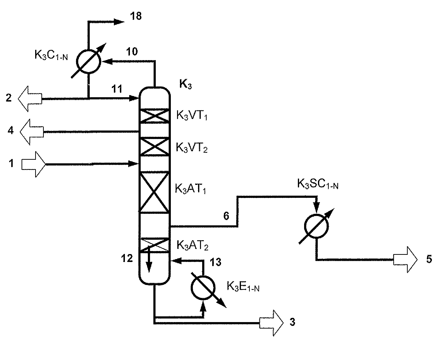
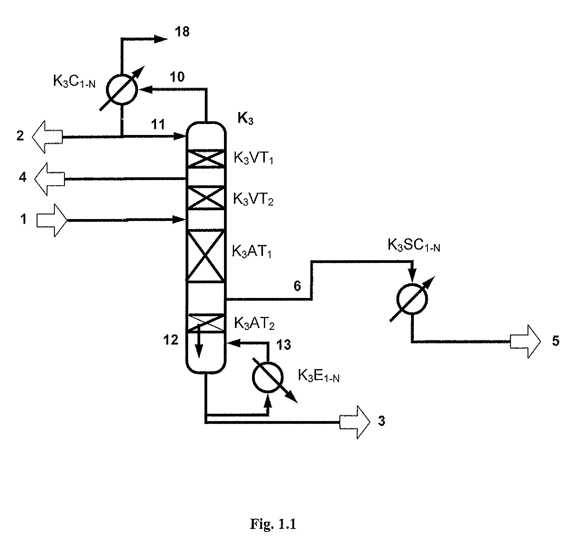
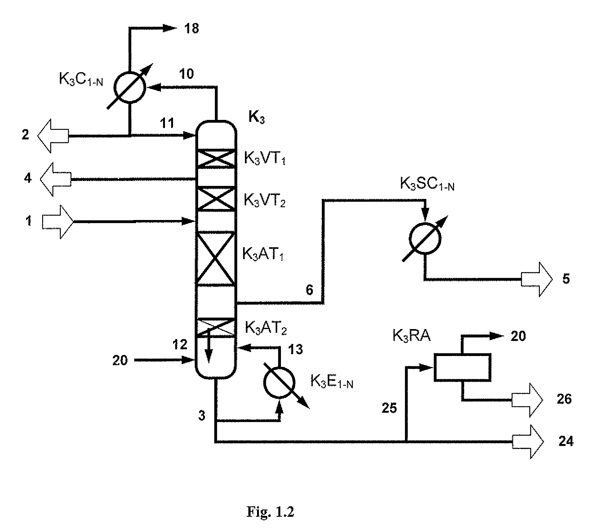
[0181]For this example, a dividing wall column according to FIG. 3.1 is used. The dividing wall column K3 consists of a rectifying section with 2 sections. The upper section K3VT1 has a separating performance of 2 theoretical plates, the section K3VT2 below it a separating performance of 12 theoretical plates. Below the upper rectifying section K3VT1 there is the possibility of withdrawing a liquid stream (4) to discharge diphenyl ether.

[0182]Below the rectifying section, the column is partitioned by a vertical dividing wall T. On the withdrawal side and feed side of this dividing wall are in each case disposed at least 2 sections. The feed (1) is introduced on the feed side of the dividing wall. A liquid withdrawal of the purified diphenyl carbonate (5) is effected on the withdrawal side.

[0183]The upper section K3TLO disposed on the feed side of the dividing wall serves for the removal of high boilers which...

example 3

DPC Purification in a Dividing Wall Column with Vaporous Sidestream Withdrawal

[0190]For this example, a dividing wall column according to FIG. 3.2 is used. The dividing wall column K3 consists of a rectifying section with 2 sections. The upper section K3VT1 has a separating performance of 2 theoretical plates, the section K3VT2

[0191]below it a separating performance of 13 theoretical plates. Below the upper rectifying section K3VT1, there is the possibility of withdrawing a liquid stream (4) to discharge diphenyl ether.

[0192]Below the rectifying section, the column is partitioned by a vertical dividing wall T. On the feed side and the withdrawal side of this dividing wall are in each case disposed at least 2 sections. On the feed side of the dividing wall, the feed (1) is introduced. On the withdrawal side, there is a vaporous withdrawal of the purified diphenyl carbonate (6).

[0193]The upper section K3TLO disposed on the feed side of the dividing wall serves for the removal of high...


PUM

PropertyMeasurementUnit
Fractionaaaaaaaaaa
Diameteraaaaaaaaaa
Boiling pointaaaaaaaaaa

Abstract

Processes comprising: transesterifying a dialkyl carbonate and an aromatic hydroxyl compound in the presence of a transesterification catalyst to provide a diaryl carbonate product comprising the transesterification catalyst as an impurity; subjecting the diaryl carbonate product to distillation in a first distillation column having an upper part and a lower part, wherein the upper part comprises a rectifying section and the lower part comprises a stripping section; and withdrawing a first sidestream from the first distillation column, wherein the first sidestream comprises a purified diaryl carbonate.

Description

BACKGROUND OF THE INVENTION[0001]The purification of diaryl carbonates is of great significance owing to the high requirements on the purity thereof for the preparation of qualitatively high-value polycarbonates by melt transesterification, Diaryl carbonates prepared from transesterification of an aromatic hydroxyl compound with an alkyl carbonate may comprise both high-boiling and medium-boiling secondary components, and also catalyst residues, as impurities. High-boiling components—often also referred to as high boilers—in the context of such preparation processes are those whose boiling points are above that of the diaryl carbonate. Medium-boiling components—often also referred to as intermediate boilers—in the context of such preparation processes are those whose boiling points are between that of the diaryl carbonate and that of the alkyl aryl carbonate which can be formed as a by-product during the preparation of the diaryl carbonate. All of these impurities can lead to consid...

Claims


Application Information

Patent Timeline
IPC IPC(8): C07C68/06
CPCB01D3/14B01D3/141C07C68/08C07C69/96Y02P20/50
Inventor OOMS, PIETERRECHNER, JOHANNBOHM, MATTHIASDUX, ANDREHALLENBERGER, KASPARRONGE, GEORGVANDEN EYNDE, JOHAN
Owner COVESTRO DEUTSCHLAND AG
Learn More