Suspension device and method for use with a vehicle
a suspension device and vehicle technology, applied in the direction of shock absorbers, instruments, cycle equipment, etc., can solve the problems of vehicle inclination to a greater extent, wheel starting to bounce, lifting of inner wheels, etc., and achieve the effect of improving the running characteristics of the vehicl
- Summary
- Abstract
- Description
- Claims
- Application Information
AI Technical Summary
Benefits of technology
Problems solved by technology
Method used
Image
Examples
first embodiment
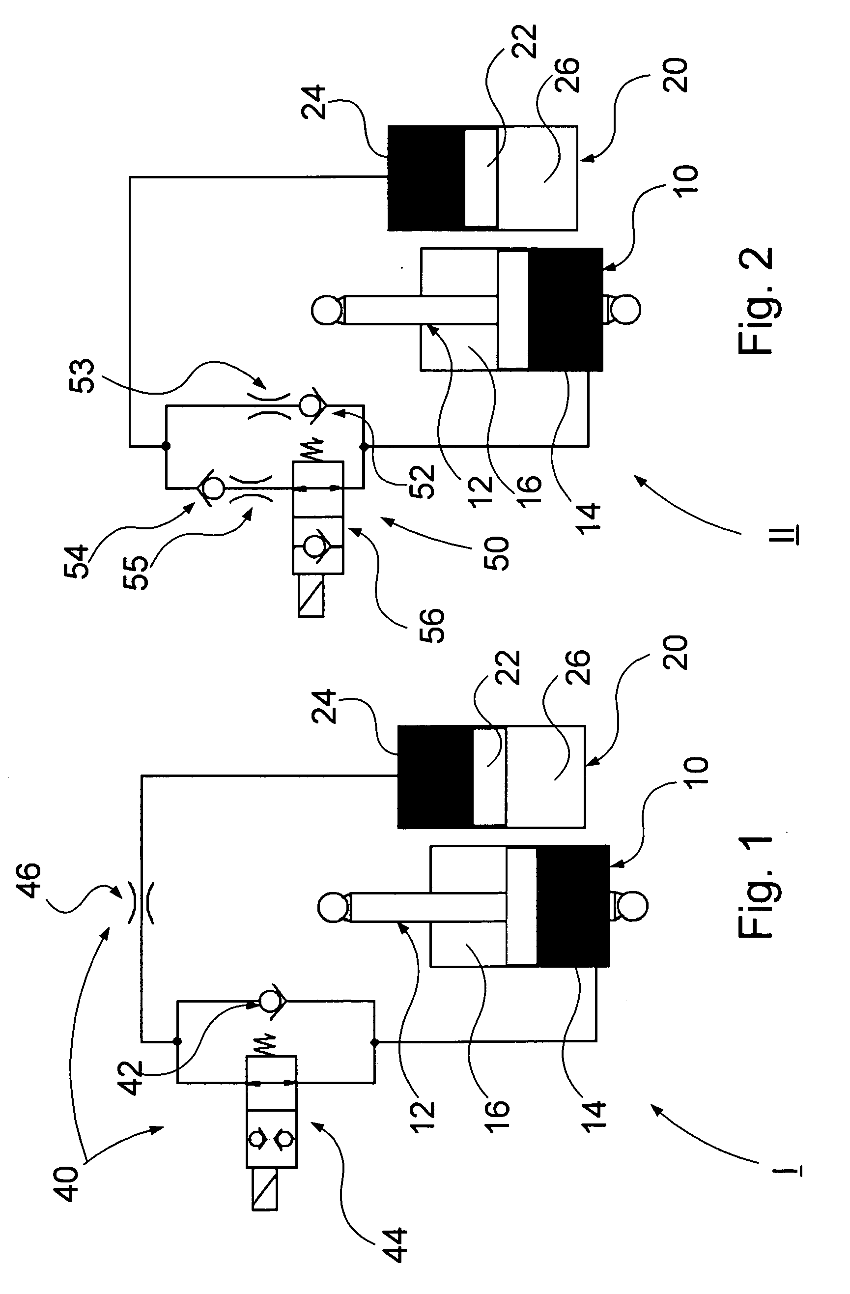
[0037]FIG. 1 schematically shows a suspension device I according to the present invention. The suspension device I comprises in- and out-configurations, respectively. The suspension device I comprises a first space 10 and a second space 20 separated by means of a valve configuration 40, which is in fluid communication with the first and the second spaces, the valve configuration 40 being arranged to control the flow of the fluid between the first and second spaces.
[0038]The suspension device I further comprises a piston stem 12 glidably arranged in the first space. The piston stem 12 is intended to be connected to a wheel of the vehicle via a linkage. The piston stem 12 is arranged in the first space 10 in such a way that it is divided into a first cavity 14 and a second cavity 16, the first cavity 14 being in fluid communication with the valve configuration 40 and containing a first fluid, preferably oil, and the second cavity containing a second fluid in the form of a gaseous medi...
second embodiment
[0046]The valve configuration 50 comprises a first pair of valves 52, 53, a second pair of valves 54, 55 and a controllable valve member 56. The first pair of valves is arranged parallel to the second pair of valves. The first pair of valves comprises a first non-return valve 52 and a first throttle valve 53 arranged in series. The second pair of valves comprises a second non-return valve 54 and a second throttle valve 55 arranged in series. The controllable valve member 56 is arranged in series with the second valve member 54, 55.
[0047]The first non-return valve 52 is arranged to allow oil through from the first cavity 14 during compression, i.e. during movement of the piston stem in the direction of compression, i.e. during retraction of the piston stem 12. The first non-return valve 52 is further arranged not to allow oil through the third cavity 24 during expansion, i.e. during movement of the piston in the direction of expansion, i.e. during extension of the piston stem 12.
[00...
third embodiment
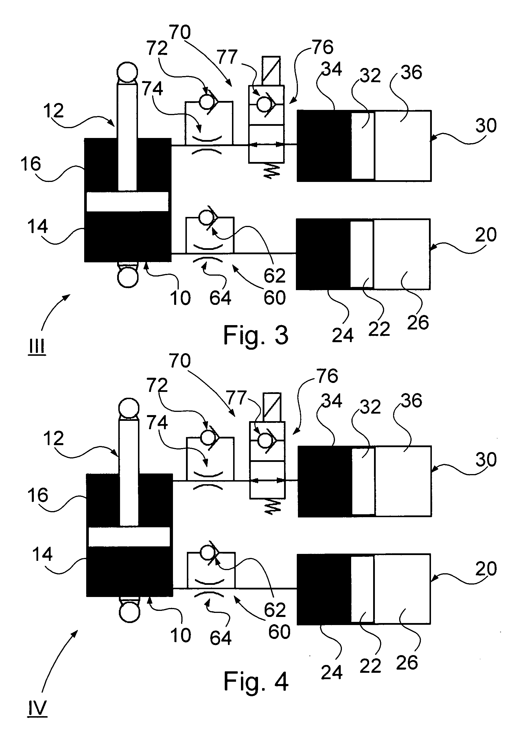
[0052]FIG. 3 schematically shows a suspension device III according to the present invention. The suspension device III comprises in- and out-configurations, respectively. The suspension device III for a vehicle comprises a first space 10, a second space 20 and a third space 30. The first space 10 and the second space 20 are separated by means of a first valve configuration 60, which is in fluid communication with the first space 10 and second space 20, the first valve configuration 60 being arranged to control the fluid between the first space 10 and second space 20. The first space 10 and the third space 30 are separated by means of a second valve configuration 70, which is in fluid communication with the first space 10 and third space 30, the second valve configuration 70 being arranged to control the fluid between the first space 10 and the third space 30.
[0053]The suspension device III further comprises a piston stem 12 glidably arranged in the first space 10. The piston stem 12...
PUM
 Abstract
Description
Claims
Application Information
 - R&D
- Intellectual Property
- Life Sciences
- Materials
- Tech Scout
- Unparalleled Data Quality
- Higher Quality Content
- 60% Fewer Hallucinations
Browse by: Latest US Patents, China's latest patents, Technical Efficacy Thesaurus, Application Domain, Technology Topic, Popular Technical Reports.
© 2025 PatSnap. All rights reserved.Legal|Privacy policy|Modern Slavery Act Transparency Statement|Sitemap|About US| Contact US: help@patsnap.com


